Systems and methods for improving penetration of radiographic scanners
A technology of penetrating power and inspection system, applied in the field of increasing the penetrating power of the radiological imaging system and reducing the exclusion area, which can solve the problems of reducing the penetrating power and reducing the source intensity, etc.
- Summary
- Abstract
- Description
- Claims
- Application Information
AI Technical Summary
Problems solved by technology
Method used
Image

Examples
Embodiment Construction
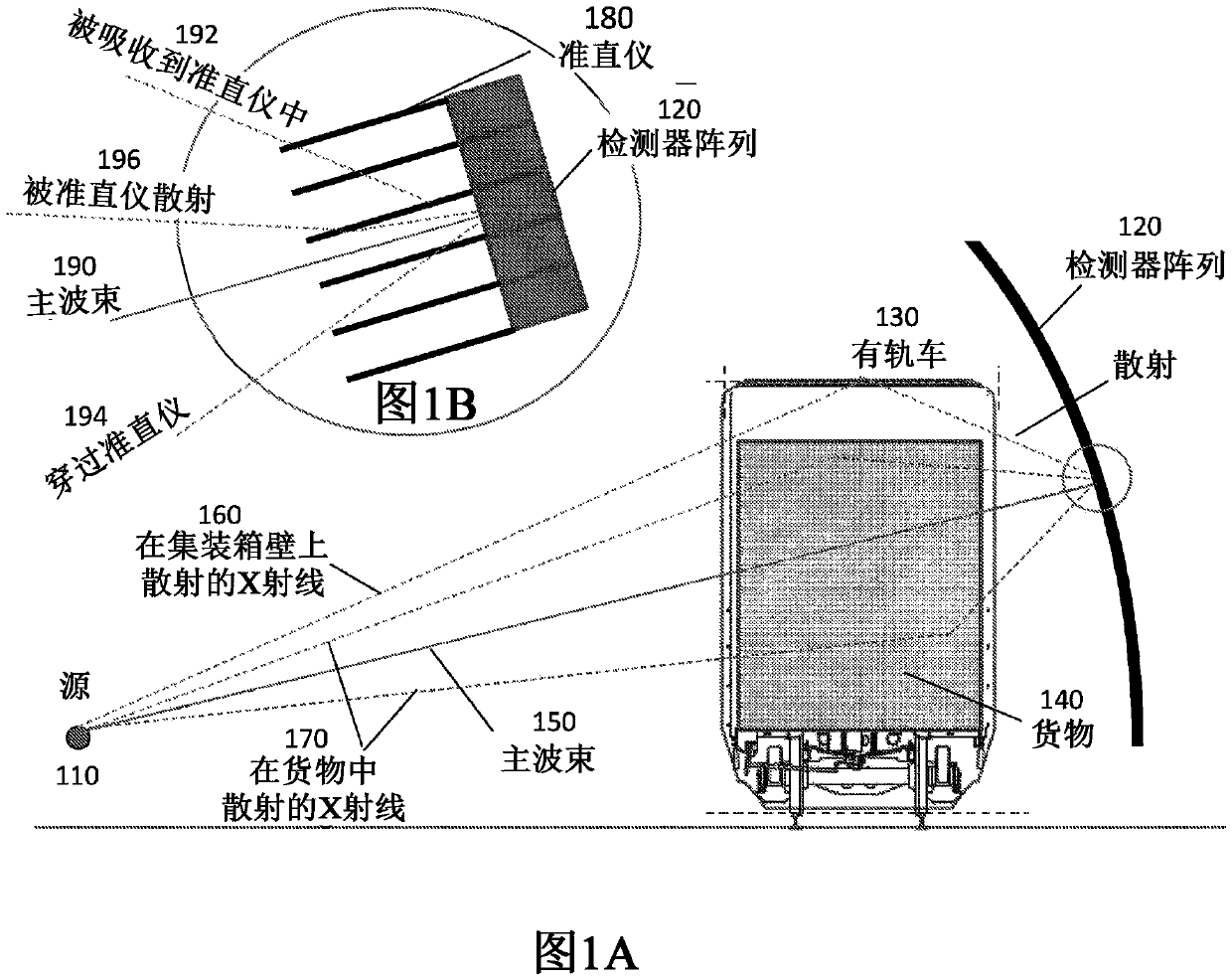
[0062] This specification describes scanning systems with increased penetration capabilities and smaller exclusion areas, resulting in improved performance and ease of deployment in a wide range of environments. Embodiments of the present specification are well suited for applications in environments including, but not limited to, container, truck, and rail car inspections. Some embodiments of the present description are particularly well suited for use when inspecting slow moving vehicles.
[0063] The present specification is directed to systems and methods for reducing the exclusion zone and increasing the penetration capabilities of radiation imaging systems, such as X-ray scanners. In embodiments, the imaging systems described herein are capable of scanning high densities of cargo with sufficient penetration depth to detect contraband, resulting in a low probability of dark alerts (which may require a second inspection). This specification also describes an imaging syste...
PUM
 Abstract
Description
Claims
Application Information
PatSnap Eureka turns technology decisions into work you can execute. Powered by our Innovation Knowledge Graph, it runs expert workflows across engineering, life sciences, materials and intellectual property. Get your review-ready output in minutes.


