Pipe pile waste heat recovery system

A technology of waste heat recovery system and pipe pile, which is applied in the direction of steam engine device, steam application, machine/engine, etc. It can solve the problems of low steam recovery efficiency, heat waste of pipe pile, heat waste of condensed water, etc., and achieve good energy saving effect

Pending Publication Date: 2019-04-30
陈建文
View PDF0 Cites 5 Cited by
  • Summary
  • Abstract
  • Description
  • Claims
  • Application Information

AI Technical Summary

Problems solved by technology

[0004] Those skilled in the art conduct analysis in conjunction with the flow of the existing process. Since the autoclave waiting for gas supply is at room temperature, after the steam is poured in, most of it will be converted into condensed water. According to actual statistics, the 10 kg pressure to be cooled After the pressure between the autoclave and the normal pressure autoclave to be heated is about 3 kg, pour about 3 kg of steam from the autoclave to be cooled into the steaming tank, and finally when about 1 kg, the autoclave and The pressure balance between the steaming tanks can no longer be reversed, and can only be discharged into the air, so that the recovery efficiency of steam is significantly reduced, and the heat of the pipe piles in the autoclave to be cooled is also wasted. The heat of the condensed water is also wasted

Method used


Image

  • Pipe pile waste heat recovery system
  • Pipe pile waste heat recovery system
  • Pipe pile waste heat recovery system

Examples


Embodiment 1

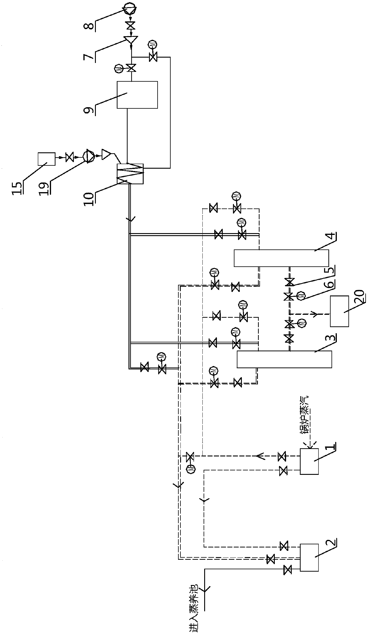
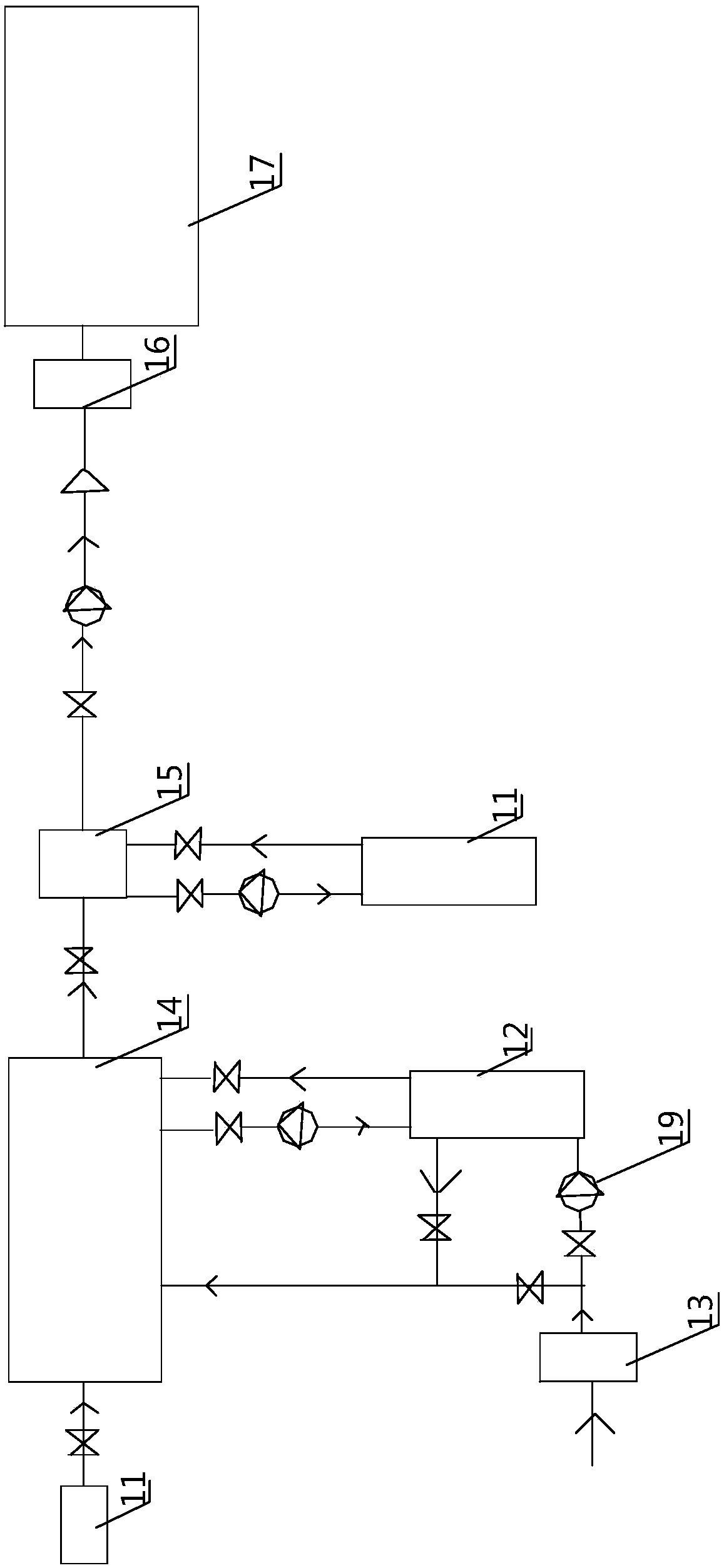
[0038] like Figure 1-5 As shown, in the waste heat recovery system for pipe piles described in Embodiment 1 of the present invention, the purpose of the technical means implemented is to solve the problem of heat waste existing in the production process of pipe piles and to use these waste heat in a reasonable and effective manner. It can be guided and utilized to make it play a role in improving the efficiency of the entire system, and on the basis of solving this technical problem, it can overcome the defect of low steam utilization rate in the original production process and make it help to improve the boiler heating efficiency.

[0039] In order to embody the advantages of the technical means adopted in the present invention, it is now specifically analyzed by comparing with the current pipe pile production process: (in the technical scheme of the present invention, due to all gate valves, check valves, electric valves and other valve components, their respective Therefor...

Embodiment 2

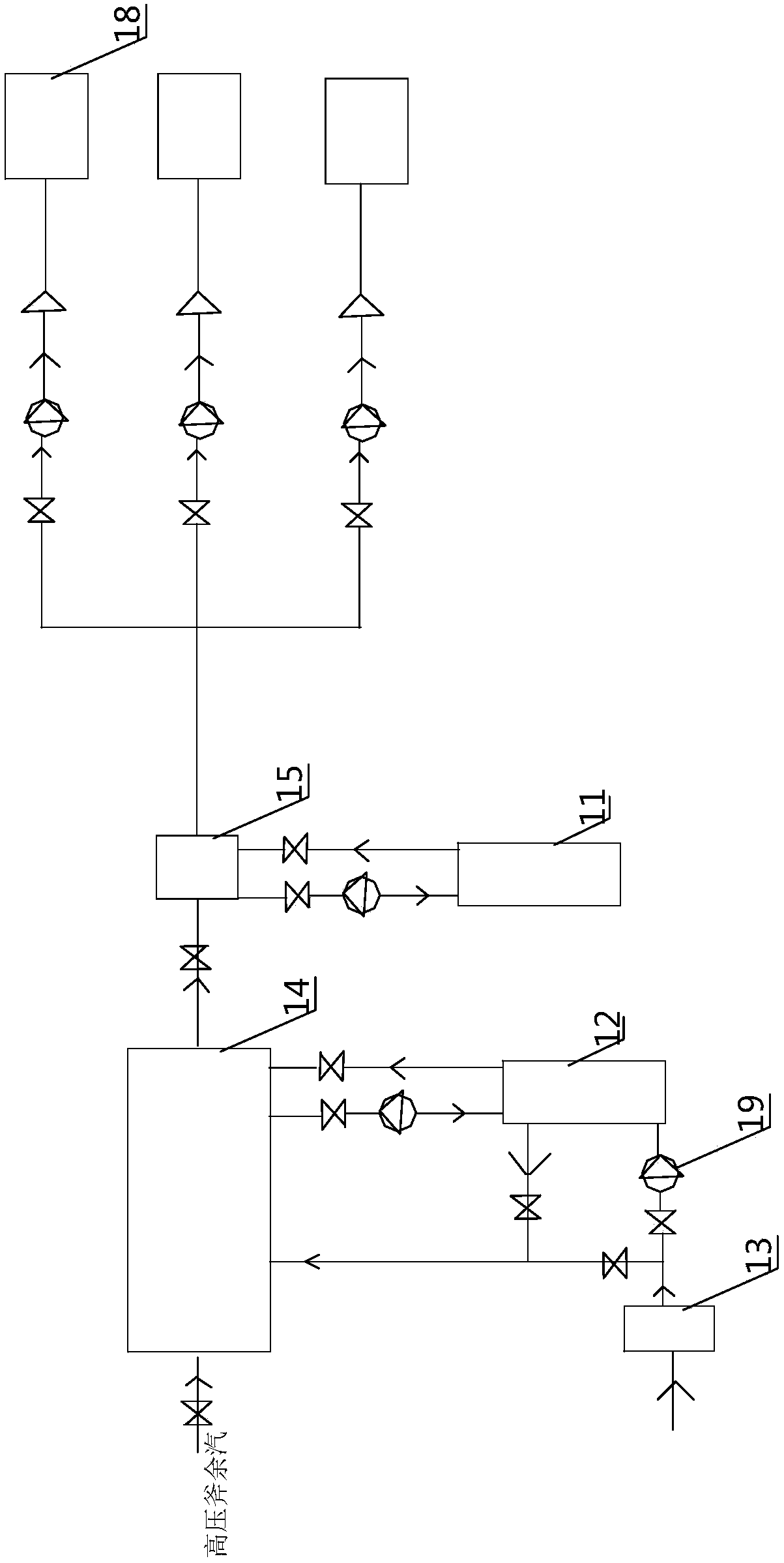
[0056] like image 3 As shown, the pipe pile waste heat recovery system described in Embodiment 2 of the present invention is a further supplement based on the technical means implemented in Embodiment 1. It belongs to the same concept as the technical solution adopted in Embodiment 1 and solves the same problem. The specific implementation content is as follows: the implemented waste steam-water heat exchanger I11 can also be equipped with three steam desuperheating and pressure reducing devices 18, and the hot water stored in the high-temperature water storage tank 15 is used to spray the three The steam desuperheating and pressure reducing device 18 is used to reduce the temperature of the external ultra-high temperature and high pressure steam, and convert the ultra-high temperature and high pressure steam into three kinds of steam of high temperature 180-200°C, medium temperature 130-150°C, and low temperature 110-120°C with a pressure of 10 kg. Low temperature 110-120°C ...


PUM


Abstract

The invention relates to a pipe pile waste heat recovery system. The pipe pile waste heat recovery system is used for the scene at least having a high-pressure kettle, a boiler or super-high-temperature high-pressure steam. The pipe pile waste heat recovery system comprises a waste steam-water heat exchanger I, a waste water heat exchanger II and a high-temperature air compressor, wherein the waste steam-water heat exchanger I is used for storing waste water and waste gas discharged from the high-pressure kettle to be cooled, and water in a high-temperature water storage tank and high-temperature compressed air are heated through the heat of the stored hot water; the waste water heat exchanger II is connected with a boiler water tank, and water in the water tank is heated by adopting the heat of condensate water of a steam curing pool and low-temperature water of the waste steam-water heat exchanger I; and high-temperature compressed air generated by the high-temperature air compressoris added into high-temperature water, and then is heated again through a boiler tail smoke heat exchanger to form external steam with the temperature being 110 DEG C or above and to be stored in a high-temperature high-pressure gas storage tank. According to the pipe pile waste heat recovery system, the boiler tail smoke, the waste steam-water of the high-pressure kettle, the condensation water of the steam curing pool and the heat of a pile in the high-pressure kettle to be cooled are fully utilized, so that the energy-saving effect is good; and the pipe pile waste heat recovery system is suitable for various occasions.

Description

technical field [0001] The invention relates to a prestressed pipe pile manufacturing process, in particular to a pipe pile waste heat recovery system. Background technique [0002] Prestressed concrete pipe piles can be divided into post-tensioned prestressed pipe piles and pretensioned prestressed pipe piles. When making prestressed pipe piles, first mix the well-proportioned concrete and put it into the pipe mold, then carry out mold closing, tensioning, and centrifugal molding, and then put it into the steam curing pool and add steam for normal pressure steam curing (temperature 60 -85°C, the total time is about 6 hours), after the atmospheric pressure steam curing is completed, the pipe mold is removed, and the pipe pile is pulled into the autoclave for high temperature and high pressure steam curing (temperature 175-185°C, pressure 1.0Mpa, The total time is about 10 hours), and the pipe piles are finished products after being steamed at high temperature and high press...

Claims


Application Information

Patent Timeline
Patent Type & Authority Applications(China)
IPC IPC(8): F01K27/02F01K21/00F01K17/02F01K3/00
CPCF01K27/02F01K3/006F01K17/02F01K21/00
Inventor 陈建文
Owner 陈建文
Why Eureka
Try Eureka