Wavelength division multiplexing passive optical network system capable of realizing interactive communication between optical network units
An optical network unit and passive optical network technology, applied in the field of optical communication, can solve the problems of interactive communication efficiency and flexibility limitations, network scale and network reliability limitations, and the difficulty of implementing interactive communication.
- Summary
- Abstract
- Description
- Claims
- Application Information
AI Technical Summary
Problems solved by technology
Method used
Image
Examples
Embodiment 1
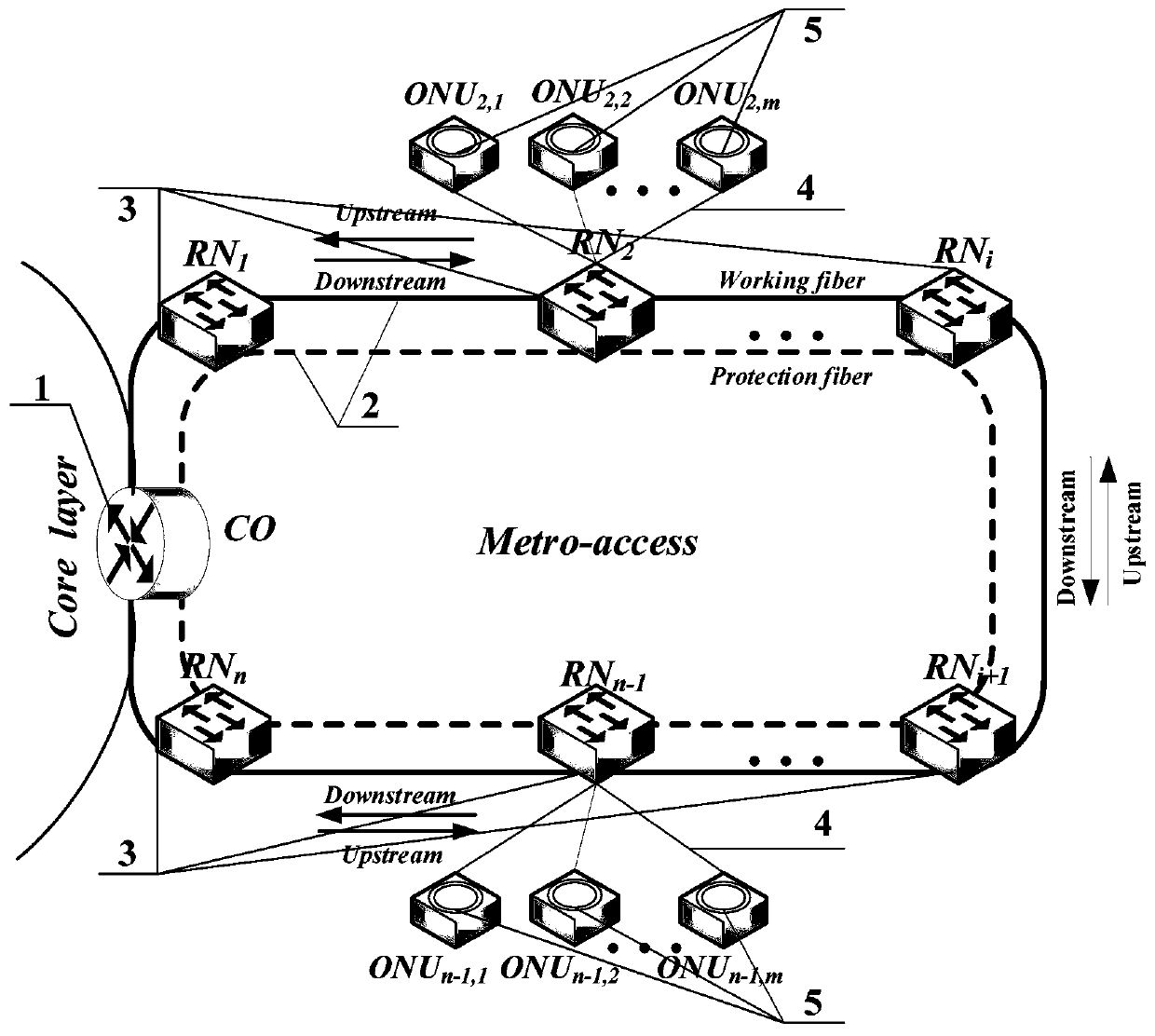
[0031] see figure 1, the WDM-PON system for interactive communication between the ONUs, the central office CO (1) connects n remote nodes RN (3) through the feeder fiber (2) to form a dual-fiber ring structure; each remote node RN (3) Connect m optical network units ONU (5) through distribution optical fiber (4).
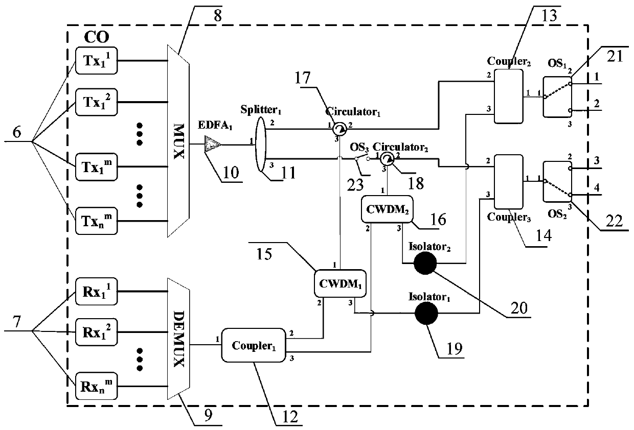
[0032] see figure 2 , the central office CO (1) includes n × m optical transmitters (6) and n × m optical receivers (7), a pair of wavelength division multiplexers (8) and demultiplexers (9 ), an erbium-doped fiber amplifier EDFA (10), a first optical splitter (11), the first, second, and third optical couplers (12, 13, 14), the first, and the second 2 A coarse wavelength division multiplexer CWDM (15, 16), the first and the second two optical circulators (17, 18), the first and the second two optical isolators (19, 20), the first and the second 2. The third three optical switches (21, 22, 23).
[0033] In CO(1), n×m optical transmitters (6) are connected to a ...
Embodiment 2
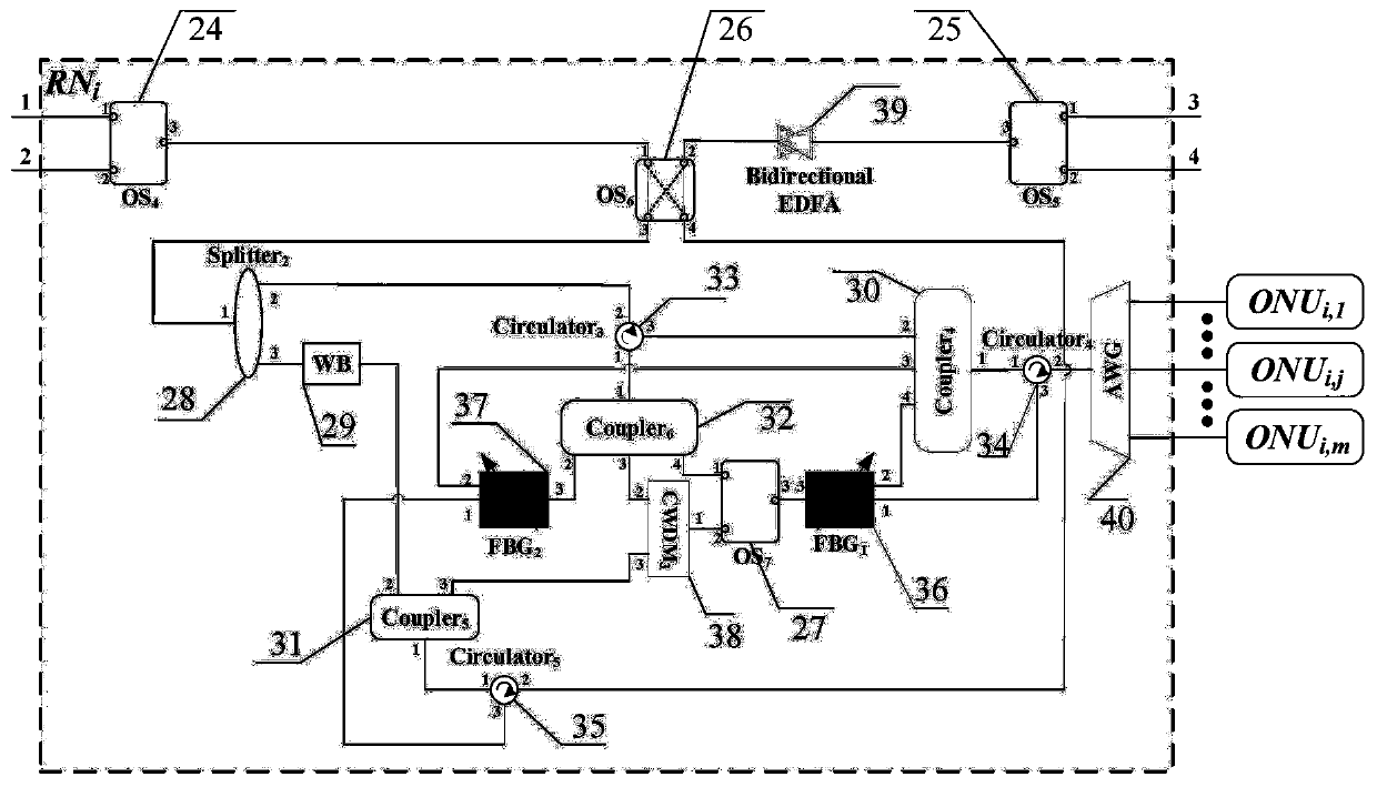
[0039] see figure 1 , figure 2 , image 3 with Figure 4 The system shown, optical network unit ONU ij with ONU ik The specific implementation method of inter-interactive communication is: optical network unit ONU ij The first tuned transmitter (45) in (5) sends an optical signal in the blue wave band After passing through the sixth optical circulator (43), enter the fourth coarse wavelength division multiplexer (41), and pass through the ONU ij (5) with RN i (3) after the distributed optical fiber (4), the optical signal is transmitted to the RN i (3). in RN i (3), the optical signal It first passes through the arrayed waveguide grating AWG (40), passes through the fourth optical circulator (34), and then reaches the first tuned fiber Bragg grating (36). Since the Bragg wavelength of the first tuned fiber Bragg grating (36) is set to So light signal The 2-port reflection from the first tuned fiber Bragg grating (36) is output to the fourth optical coupler ...
Embodiment 3
[0041] see figure 1 , figure 2 , image 3 with Figure 4 The system shown, optical network unit ONU ij with ONU rs The specific implementation method of inter-interactive communication is: optical network unit ONU ij The second tuned transmitter (47) in (5) sends out an optical signal in the blue band After the seventh optical circulator (44), enter the fourth coarse wavelength division multiplexer (41), pass through the ONU ij (5) with RN i (3) after the distributed optical fiber (4), the optical signal is transmitted to the RN i (3). in RN i (3), the optical signal It first passes through the arrayed waveguide grating AWG (40), passes through the fourth optical circulator (34), and then reaches the first tuned fiber Bragg grating (36). Since the Bragg wavelength of the first tuned fiber Bragg grating (36) is not So light signal Output from port 3 of the first tuned fiber Bragg grating (36) to the seventh optical switch (27). at this time,
[0042] A. If...
PUM
 Abstract
Description
Claims
Application Information
 - R&D
- Intellectual Property
- Life Sciences
- Materials
- Tech Scout
- Unparalleled Data Quality
- Higher Quality Content
- 60% Fewer Hallucinations
Browse by: Latest US Patents, China's latest patents, Technical Efficacy Thesaurus, Application Domain, Technology Topic, Popular Technical Reports.
© 2025 PatSnap. All rights reserved.Legal|Privacy policy|Modern Slavery Act Transparency Statement|Sitemap|About US| Contact US: help@patsnap.com


