Method for operating a hybrid vehicle

A hybrid vehicle and transmission technology, which is applied in the arrangement of multiple different prime movers of hybrid vehicles and general power units, and the use of engine-driven traction, etc., can solve the problem of heavy energy storage devices, not too large, expensive, etc. problem, to achieve the effect of simple safety requirements

Active Publication Date: 2019-05-03
VOITH PATENT GMBH
View PDF10 Cites 2 Cited by
  • Summary
  • Abstract
  • Description
  • Claims
  • Application Information

AI Technical Summary

Problems solved by technology

In commercial vehicles, which are typically much heavier than this, this requires very large and thus expensive and heavy energy storage devices, which is disadvantageous, especially when the hybrid system of the vehicle is to be used as a so-called mild hybrid when designed as a hybrid powertrain, that is, as a hybrid system suitable only for supporting driving and not exclusively for electric driving of the vehicle, since such hybrid systems are typically used for energy storage devices that are not too large

Method used


Image

  • Method for operating a hybrid vehicle
  • Method for operating a hybrid vehicle
  • Method for operating a hybrid vehicle

Examples


Embodiment Construction

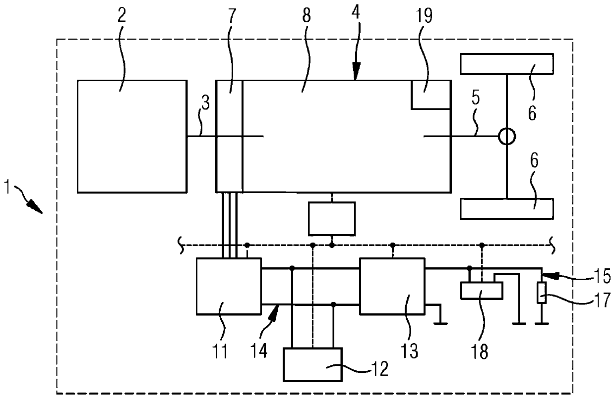
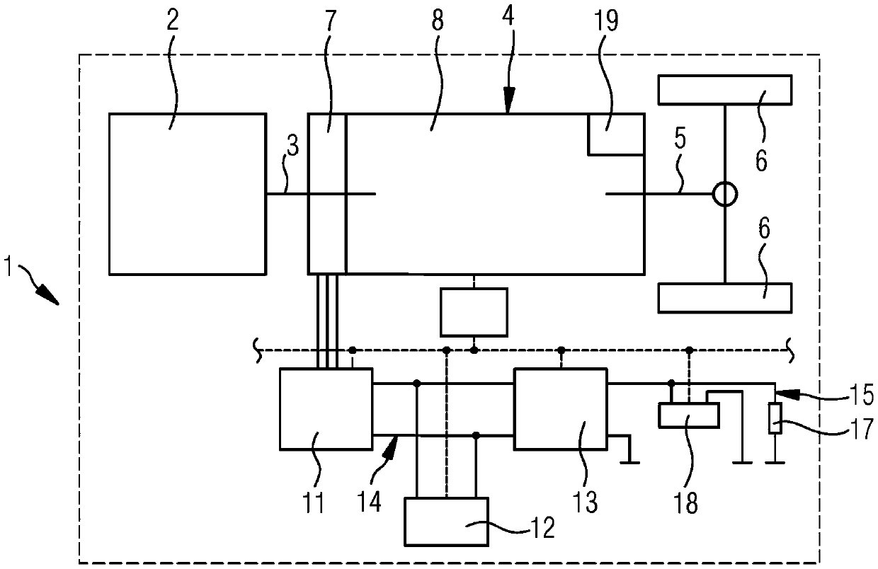
[0025] exist figure 1 A hybrid vehicle 1 is schematically indicated in the illustration of . It is driven by an internal combustion engine 2, for example a diesel engine or a gasoline engine. Via an input shaft 3 , the internal combustion engine is connected to a transmission system 4 , which contains and controls all functions of the hybrid drive apart from the internal combustion engine 2 . The transmission system 4 is connected via an output shaft 5 to two designated driven wheels 6 . Part of the transmission system 4 is here an electric machine 7 and a transmission 8 , for example an automatic transmission with a differential converter. The transmission 8 can have a hydraulic retarder T as a wear-free permanent brake 9 . Another part of the transmission system 4 is the electrical control. For this purpose there is a transmission control unit 9 which is connected via a bus system 10 , preferably a CAN bus, to a vehicle control unit (not shown here). Another part of th...


PUM


Abstract

The invention relates to a method for operating a hybrid vehicle (1), which is operated with an internal combustion engine, an electric machine (7) and a transmission, the transmission being connectedto said internal combustion engine via an input shaft, a first electrical network, a second electrical network as an on-board network, which is operated on a lower voltage level than the first electrical network, the first electrical network being operated at a higher voltage level than the second electrical network. The following elements are operated while being coupled to the first electricalnetwork: the electrical machine, an electrical energy storage device, and an energy converter which transfers electrical power at least from the first electrical network to the second electrical network, an alternator being dispensed with in the second electrical network. The invention is characterized in that the first electrical network is designed as part of a transmission system which is actuated together with the components coupled thereto by means of a transmission control device, wherein power is generated by the electrical machine, and wherein the energy supply of the second electricalnetwork has a higher priority during power distribution than a motor support of the drive of the input shaft by the electrical machine.

Description

technical field [0001] The invention relates to a method for operating a hybrid vehicle according to the type defined in detail in the preamble of claim 1 . Background technique [0002] Hybrid vehicles are already known from the general prior art in the field of passenger vehicles. Hybrid vehicles are also increasingly being used in the field of commercial vehicles, for example in small commercial vehicles or especially in commercial vehicles that are frequently started and stopped. Such a commercial vehicle can be, for example, a transport vehicle or, in particular, a bus, mainly a bus that travels within a city on a bus line service. [0003] In principle, it is known from the general prior art to dispense with a generator in hybrid vehicles. Thus, the electrical energy supply to the vehicle electrical system is carried out by the hybrid system, for example, by causing an energy converter, in particular a DC / DC converter, to convert power from the voltage level of the e...

Claims


Application Information

Patent Timeline
Patent Type & Authority Applications(China)
IPC IPC(8): B60K6/485B60K6/48B60W10/26B60W20/11B60W20/13B60W20/19B60W20/40B60W30/192B60W10/11B60W10/18B60L7/14B60L7/24B60L50/15B60K6/26
CPCB60K6/48B60L7/14B60L7/24B60W10/06B60W10/08B60W10/11B60W10/18B60W10/196B60W10/26B60W30/18127B60W30/192B60K2006/268B60K2006/4825B60L2200/18B60L2200/36B60L2240/445B60L2240/486B60L2240/547B60L2260/46B60L2260/54B60W2300/10B60W2300/12B60W2510/068B60W2510/083B60W2510/1005B60W2510/18B60W2510/244B60W2510/305B60W2710/0694B60W2710/18B60W20/40B60W20/13B60W20/11B60W20/16B60L50/15B60L58/14B60L58/13B60L58/20Y02T10/62Y02T10/70Y02T10/7072B60K6/26B60K6/485
Inventor 维塔利·拉扎尔恩卡约亨·林登迈尔约翰尼斯·格特贝恩德·格罗斯
Owner VOITH PATENT GMBH
Why Eureka
Try Eureka