spark plug
A technology for spark plugs and main parts, applied in the field of spark plugs, can solve problems such as inability to detect with good accuracy, and achieve the effects of suppressing spark consumption, suppressing pre-ignition, and ensuring detection sensitivity
- Summary
- Abstract
- Description
- Claims
- Application Information
AI Technical Summary
Problems solved by technology
Method used
Image

Examples
Embodiment 1
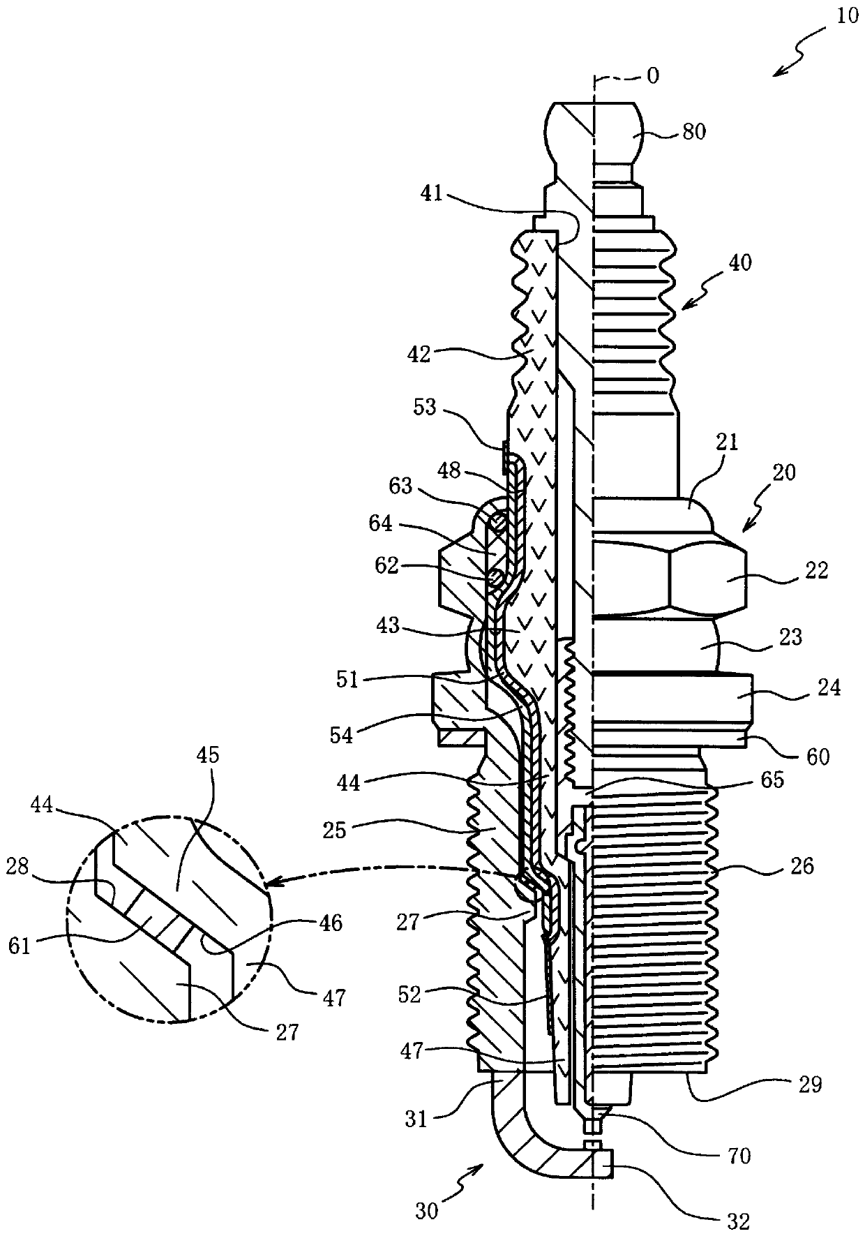
[0101] (Example 1) The experimenter took the spark plug ( figure 2 Reference) and a pressure sensor are installed on an engine with a turbocharger (displacement 1.6L). The axial front end of the detection electrode of the spark plug is located at the axial center of the small-diameter portion of the insulator, and the width W of the detection electrode in the direction perpendicular to the axis direction is 1 mm. The detection electrode is disposed on a small-diameter portion of the insulator facing the first end portion of the ground electrode.
[0102] The experimenter ignited the air-fuel mixture supplied to the engine with a spark plug to burn it. The experimenter passed the ignition device described in the first embodiment (refer to Figure 4 ) provides a potential difference between the detection electrode of the spark plug and the metal body, thereby detecting the ion current, and the generation / growth of the flame nucleus generated in the space between the insulator...
Embodiment 2
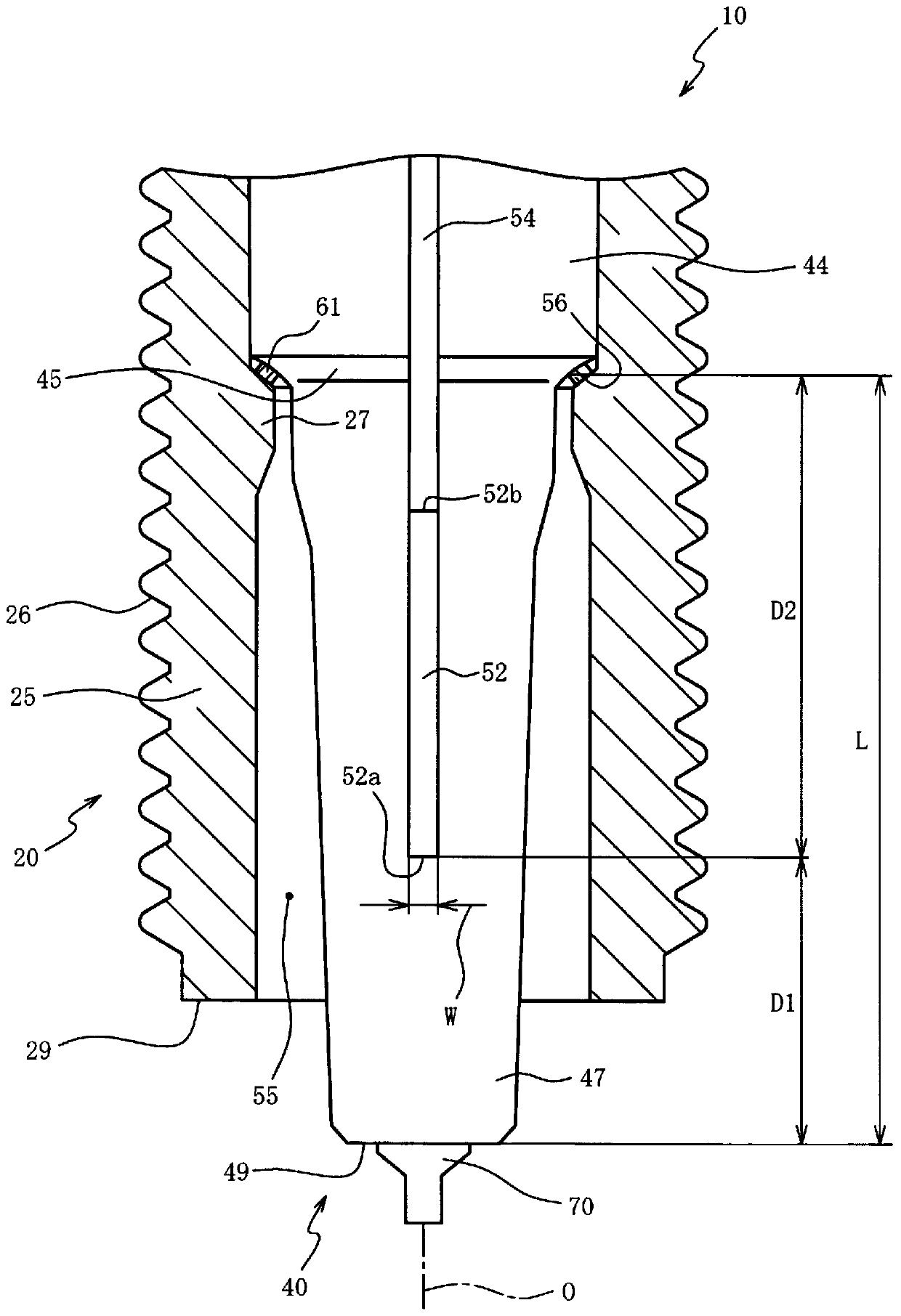
[0105] (Embodiment 2) In addition to making the width W of the detection electrode of the spark plug (refer to figure 2 ) except for various differences, the testers tested the spark plug LSPI in the same manner as in Example 1. The applied voltage (potential difference between the detection electrode and the main body) was set to +50V. Figure 14 It is a graph showing the relationship between the width of the detection electrode and the false detection rate. Depend on Figure 14 Apparently, by setting the detection electrode width to 0.5 mm or more, the misdetection rate of the spark plug LSPI can be made 10% or less. It is presumed that this is because the influence of noise or the like can be suppressed.
Embodiment 3
[0106] (Example 3) Except that the distance D1 in the axial direction from the front end of the insulator of the spark plug to the front end of the detection electrode (refer to figure 2 ) except for various differences, the testers tested the spark plug LSPI in the same manner as in Example 1. The applied voltage (potential difference between the detection electrode and the main body) was set to +50V. Figure 15 It is a graph showing the relationship between the distance D1 in the axial direction from the tip of the insulator to the tip of the detection electrode and the occurrence rate of internal flashover (discharge between the center electrode and the detection electrode). Depend on Figure 15 Obviously, by setting the distance D1 to be 6 mm or more, it is possible to detect the spark plug LSPI while preventing the occurrence of internal flashover. This is due to the enhancement of the detection sensitivity of the spark plug LSPI by suppressing the discharge between th...
PUM
 Abstract
Description
Claims
Application Information
 - R&D
- Intellectual Property
- Life Sciences
- Materials
- Tech Scout
- Unparalleled Data Quality
- Higher Quality Content
- 60% Fewer Hallucinations
Browse by: Latest US Patents, China's latest patents, Technical Efficacy Thesaurus, Application Domain, Technology Topic, Popular Technical Reports.
© 2025 PatSnap. All rights reserved.Legal|Privacy policy|Modern Slavery Act Transparency Statement|Sitemap|About US| Contact US: help@patsnap.com