A drilling liner pressure control well cementation process

A cementing and liner technology, which is applied in wellbore/well components, earthwork drilling, sealing/isolation, etc., can solve the problem of high safety risk of well control and oil and gas problems in liner cementing construction operations in formations with high and narrow safety density windows. Well Integrity The long-term safe development of oil and gas fields will affect the long-term safety development, aggravate the lost circulation and other problems, so as to reduce the risk of liner cementing construction, meet the needs of later development and production, and improve the effect of well integrity

Inactive Publication Date: 2019-05-07
PETROCHINA CO LTD
View PDF5 Cites 7 Cited by
  • Summary
  • Abstract
  • Description
  • Claims
  • Application Information

AI Technical Summary

Problems solved by technology

[0004] However, for formations with a narrow safe density window, the use of existing liner cementing techniques may easily cause or intensify lost circulation, resulting in a decrease in liquid column pressure, causing oil and gas channeling in the lower well section, and low interface cementation strength. The cementing quality is unqualified; and it is not easy to press and stabilize the high-pressure layer, and oil and gas are easy to escape; in addition, the displacement efficiency is low, and the virtual mud cake, oil film and drilling fluid on the well wall and casing wall are difficult to clean during the cementing process
The above problems often lead to high safety risk of liner cementing in formations with high and narrow safety density windows, and it is difficult to guarantee the quality of cementing, which has a great impact on the integrity of oil and gas wells and the long-term safe development of oil and gas fields

Method used


Image

  • A drilling liner pressure control well cementation process
  • A drilling liner pressure control well cementation process
  • A drilling liner pressure control well cementation process

Examples


Embodiment Construction

[0024] In order to make the technical solutions and advantages of the present invention clearer, the embodiments of the present invention will be further described in detail below in conjunction with the accompanying drawings. Unless otherwise defined, all technical terms used in the embodiments of the present invention have the same meanings as commonly understood by those skilled in the art.

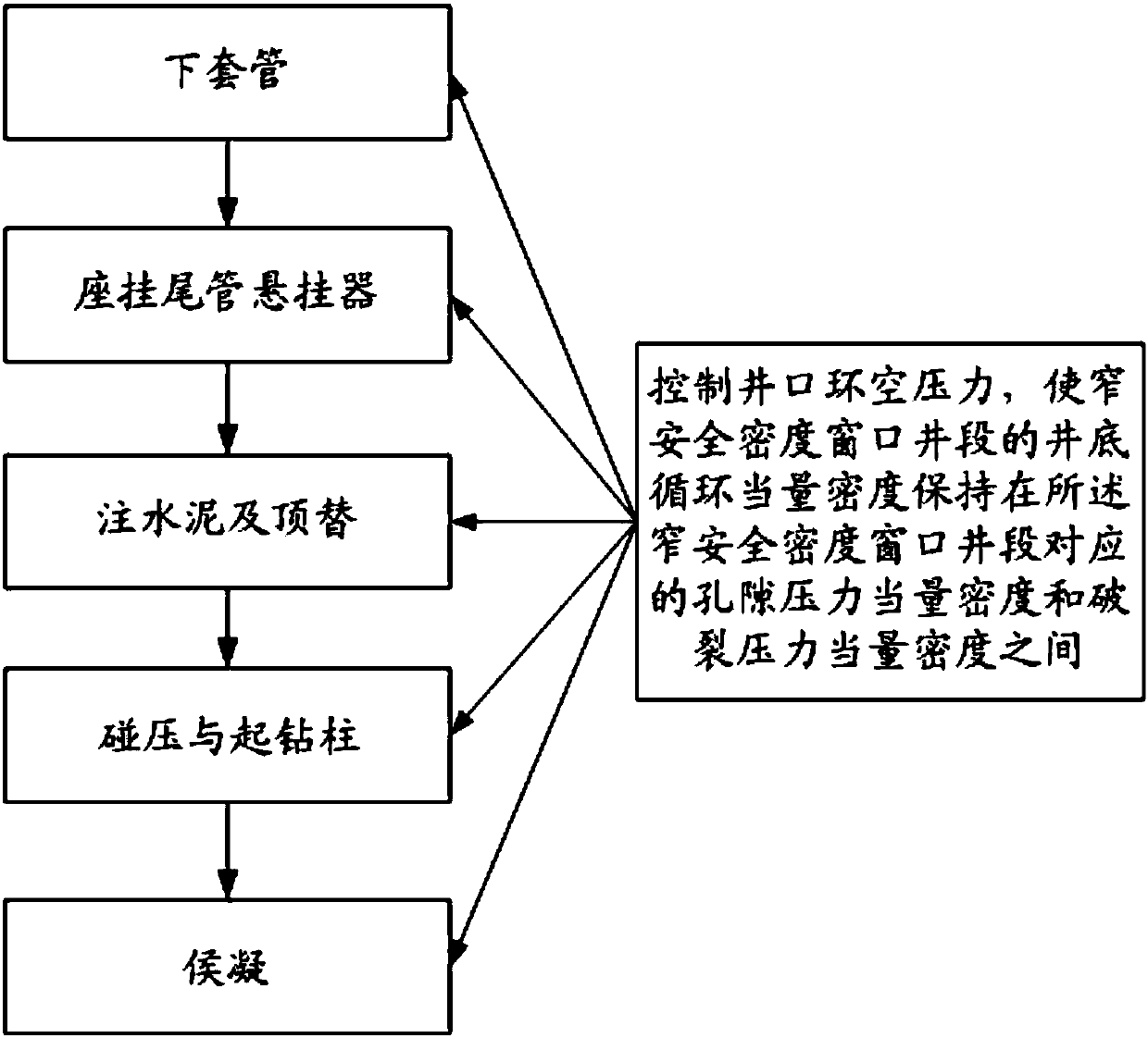
[0025] The liner is the string of casing that is run in a technically cased well and whose top does not extend to the wellhead. The liner is lowered through the drill pipe, and the drill pipe is pulled out after the cement is injected. A narrow safe density window well section means that the formation fracture pressure and formation pore pressure in this well section are not much different. The density range that can be selected for drilling fluid is very small, which is prone to drilling complications. In this range, the well wall collapses and blocks are lost. For this type of well ...


PUM


Abstract

The invention discloses a drilling liner pressure control well cementation process, and belongs to the technical field of oil and gas development well cementation. The drilling liner pressure controlwell cementation process sequentially comprises a casing running stage, a drilling liner hanger seating and hanging stage, a cementing and replacing stage, a bump pressure and drill string pulling-outstage and a setting waiting stage. In the casing running stage, the drilling liner hanger seating and hanging stage, the cement injecting and replacing stage, the bump pressure and drill string pulling-out stage and the waiting stage, the well bottom circulation equivalent density of the narrow safety density window well section is kept between the pore pressure equivalent density and the rupturepressure equivalent density corresponding to the narrow safety density window well section by controlling the wellhead annulus pressure. According to the well cementation technology, through wellheadannulus pressure control, the well bottom circulation equivalent density corresponding to the narrow safety density window well section is made to be between the pore pressure equivalent density andthe rupture pressure equivalent density, it is guaranteed that a pressure-bearing weak stratum is not pressed to leak while the oil and gas display layer is pressed stably, the drilling liner well cementation construction risk is reduced, and the well cementation quality is improved.

Description

technical field [0001] The invention relates to the technical field of well cementing for oil and gas development, in particular to a tailpipe controlled pressure well cementing process. Background technique [0002] Liner cementing is to run the casing into the well through drilling tools and other running tools, and inject cement into the annular space between the well wall and the casing. After the cement solidifies, the oil layer, gas layer and water layer in the wellbore The process of layer isolation to protect oil and gas well casings and increase the life of oil and gas wells is one of the important links in oil and gas well drilling engineering. [0003] At present, the basic process of liner cementing is to use the drill pipe to send the oil layer casing to the downhole preset position and then hang the liner hanger, then use the double rubber plug method to carry out cementing and displacement construction, and then carry out bumping and pressing. Pull out the dr...

Claims


Application Information

Patent Timeline
Patent Type & Authority Applications(China)
IPC IPC(8): E21B33/13
Inventor 郭建华李杰胡锡辉马勇曹权刘波李斌徐冰青付志沈欣宇夏连彬杨华健任锐周代生
Owner PETROCHINA CO LTD
Why Eureka
Try Eureka