An electric field traction ultrafast laser thermal cracking processing device and method for hard and brittle materials
A technology of ultra-fast laser and hard and brittle materials, which is applied in metal processing equipment, laser welding equipment, manufacturing tools, etc., can solve the problems of insufficient depth of ultra-fast laser thermal cracking and extended crack depth, etc., and achieve less fragments and less roughness Effect of small, debris-free slag burrs
- Summary
- Abstract
- Description
- Claims
- Application Information
AI Technical Summary
Problems solved by technology
Method used
Image
Examples
example 1
[0033] [Example 1] Workpiece processing of glass material, thickness 2mm, electro-acoustic coupling time > 20ps
[0034] Step 1: Device Arrangement:
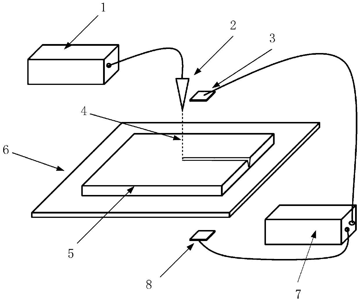
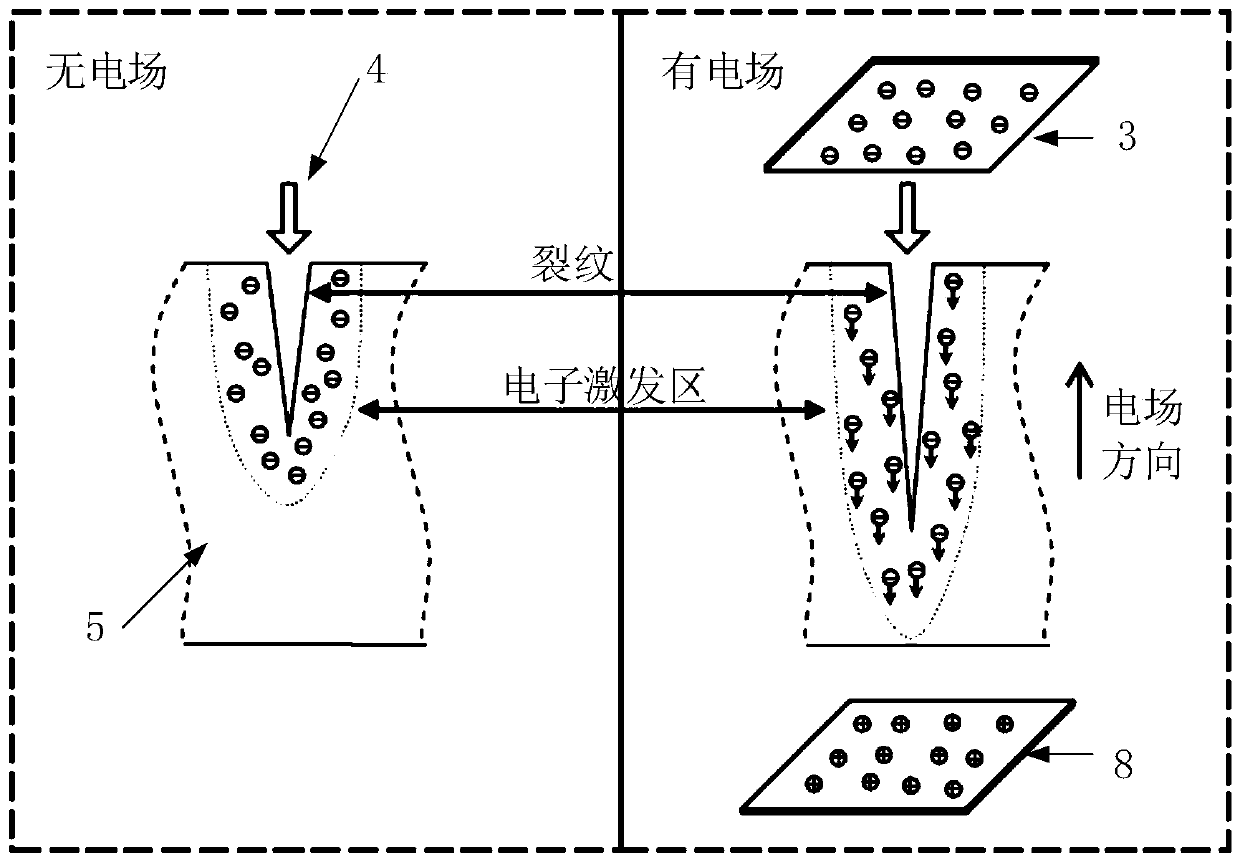
[0035] The cathode plate 3 and the laser head 2 are arranged above the workpiece 5 to be processed on the front of the insulating support plate 6, and the anode plate 8 is positioned at the back side of the insulating support plate 6 and faces the cathode plate 3; adjust the position of the laser head 2 or the cathode plate 3 so that the laser head 2. It is always located directly in front of the cathode plate 3 on the processing path, and the laser beam is positioned at the edge of the cathode plate 3.
[0036] Step 2: Parameter setting:
[0037] Ultrafast laser process parameters: power 50W, wavelength 355nm, pulse width 10ps, repetition frequency 50kHz, focus on the surface of the material;
[0038] Electric field parameters: adjust the distance between the cathode plate 3 and the anode plate 8 to 0.5cm, and the output volt...
example 2
[0042] [Example 2] Workpiece processing of sapphire material, thickness 3mm, electroacoustic coupling time > 80ps
[0043] Step 1: Device Arrangement:
[0044] The cathode plate 3 and the laser head 2 are arranged above the workpiece 5 to be processed on the front of the insulating support plate 6, and the anode plate 8 is positioned at the back side of the insulating support plate 6 and faces the cathode plate 3; adjust the position of the laser head 2 or the cathode plate 3 so that the laser head 2. It is always located directly in front of the cathode plate 3 on the processing path, and the laser beam is positioned at the edge of the cathode plate 3.
[0045] Step 2: Parameter setting:
[0046] Ultrafast laser process parameters: power 100W, wavelength 532nm, pulse width 70ps, repetition frequency 200kHz, focus on the surface of the material;
[0047] Electric field parameters: adjust the distance between the cathode plate 3 and the anode plate 8 to 1 cm, and the output v...
example 3
[0051] 【Example 3】Workpiece processing of ceramic material, thickness 5mm, electro-acoustic coupling time > 200ps
[0052] Step 1: Device Arrangement:
[0053] The cathode plate 3 and the laser head 2 are arranged above the workpiece 5 to be processed on the front of the insulating support plate 6, and the anode plate 8 is positioned at the back side of the insulating support plate 6 and faces the cathode plate 3; adjust the position of the laser head 2 or the cathode plate 3 so that the laser head 2. It is always located directly in front of the cathode plate 3 on the processing path, and the laser beam is positioned at the edge of the cathode plate 3.
[0054] Step 2: Parameter setting:
[0055] Ultrafast laser process parameters: power 200W, wavelength 1064nm, pulse width 180ps, repetition frequency 450kHz, focus on the surface of the material;
[0056] Electric field parameters: adjust the distance between the cathode plate 3 and the anode plate 8 to 4cm, and the voltage...
PUM
 Abstract
Description
Claims
Application Information
 - R&D
- Intellectual Property
- Life Sciences
- Materials
- Tech Scout
- Unparalleled Data Quality
- Higher Quality Content
- 60% Fewer Hallucinations
Browse by: Latest US Patents, China's latest patents, Technical Efficacy Thesaurus, Application Domain, Technology Topic, Popular Technical Reports.
© 2025 PatSnap. All rights reserved.Legal|Privacy policy|Modern Slavery Act Transparency Statement|Sitemap|About US| Contact US: help@patsnap.com


