
Kinematics Calibration Method of Industrial Robot Based on Coordinate Measuring Instrument

A technology of robot kinematics and coordinate measuring instrument, applied in the field of robotics, can solve problems such as parameter identification matrix dissatisfaction with rank, model dissatisfaction with continuity and minimization, identification result deviation, etc.

Active Publication Date: 2021-01-26
珞石(北京)科技有限公司
View PDF7 Cites 0 Cited by
  • Summary
  • Abstract
  • Description
  • Claims
  • Application Information

AI Technical Summary

Problems solved by technology

However, the above scheme does not consider the singularity of the model caused by the redundant parameters in the identification model, which makes the model not satisfy the continuity and minimization
At this time, the parameter identification matrix is ​​not full of rank, and the disturbance factors when measuring the position of the robot end and the angle values ​​of each joint will seriously affect the accuracy of kinematic parameter identification, resulting in a large deviation in the identification results, thus affecting the optimization effect of the robot end accuracy.
[0005] The Chinese patent publication number is CN 102294695A, which provides a robot calibration method. The calibration method of this invention has the advantage of being simple and fast. However, the optimization effect of the robot end accuracy of the calibration method of this invention is not good.

Method used


Image

  • Kinematics Calibration Method of Industrial Robot Based on Coordinate Measuring Instrument
  • Kinematics Calibration Method of Industrial Robot Based on Coordinate Measuring Instrument
  • Kinematics Calibration Method of Industrial Robot Based on Coordinate Measuring Instrument

Examples


Embodiment Construction

[0062] The following describes in detail the embodiments of the present invention, examples of which are illustrated in the accompanying drawings, wherein the same or similar reference numerals refer to the same or similar elements or elements having the same or similar functions throughout. The embodiments described below with reference to the accompanying drawings are exemplary, and are intended to explain the present invention and should not be construed as limiting the present invention.

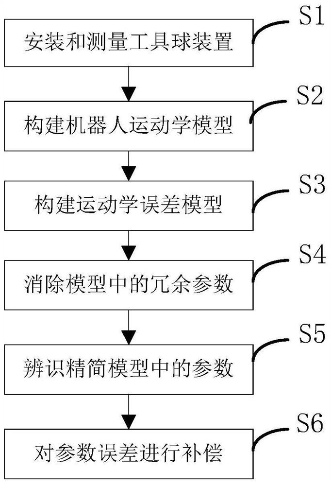
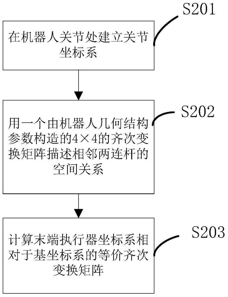
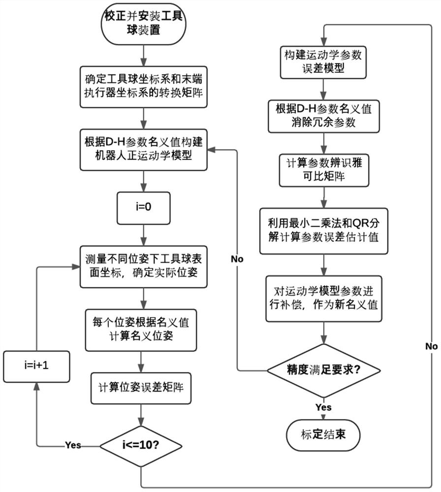
[0063] The present invention provides a kinematics calibration method of an industrial robot based on a coordinate measuring instrument. Figure 1-3 , Step S1, install and measure the tool ball device, establish a tool ball coordinate system and calculate the pose of the tool ball coordinate system.

[0064] In step S1, the tool ball device includes two parallel aluminum disks, four aluminum rods are arranged between the two aluminum disks, one of the aluminum disks is attached to the re...


PUM


Abstract

The invention provides an industrial robot kinematic calibration method based on a coordinate measuring instrument. The method comprises a main control module, a power supply module, a display module,a storage module, a bluetooth module and a positioning module. One end of the bluetooth module is connected to the main control module, and the other end of the bluetooth module is wirelessly connected with a bluetooth tag arranged on the body of a worker; the positioning module is connected with the main control module; and the main control module is connected with the display module and the storage module. Through the design of the bluetooth tag, the device is simple in structure, cheap in price, easy to integrate and can be widely used.

Description

technical field [0001] The invention relates to the technical field of robots, in particular to a kinematics calibration method of an industrial robot based on a coordinate measuring instrument. Background technique [0002] The kinematics calibration of the robot does not change the structural design of the robot, but reduces the geometric parameter errors during the production, assembly and use of the robot by modifying the robot controller software, thereby improving the absolute positioning accuracy of the robot. Robot kinematics calibration is usually divided into four steps: 1) Modeling: establish a mathematical model describing the geometric characteristics and motion performance of the robot; 2) Measurement: measure the pose of the robot end-effector in the world coordinate system; 3) Identification: based on The kinematic error model is used to identify the kinematic parameters of the robot through a reasonable algorithm; 4) Compensation: Modify the controller param...

Claims


Application Information

Patent Timeline
Patent Type & Authority Patents(China)
IPC IPC(8): G01B21/00
Inventor 张博韩建欢庹华
Owner 珞石(北京)科技有限公司
Learn More