Dynamically reconfigurable battery pack semi-matrix type topological structure, system and control method

A technology of dynamic recombination and topology structure, applied in battery circuit devices, current collectors, electric vehicles, etc., can solve problems affecting the normal operation of energy storage power stations and consume a lot of energy, and achieve the goals of improving life, saving use, and reducing power consumption Effect

Active Publication Date: 2019-05-10
STATE GRID JIANGSU ELECTRIC POWER CO ELECTRIC POWER RES INST +2
View PDF5 Cites 8 Cited by
  • Summary
  • Abstract
  • Description
  • Claims
  • Application Information

AI Technical Summary

Problems solved by technology

[0004] However, after the energy storage power station is built and connected to the grid, changing the physical location of the battery modules or battery cells in the energy st...

Method used


Image

  • Dynamically reconfigurable battery pack semi-matrix type topological structure, system and control method
  • Dynamically reconfigurable battery pack semi-matrix type topological structure, system and control method
  • Dynamically reconfigurable battery pack semi-matrix type topological structure, system and control method

Examples


Embodiment 1

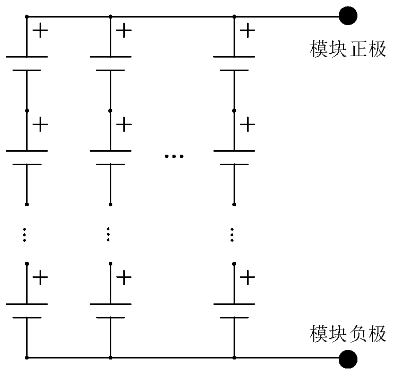
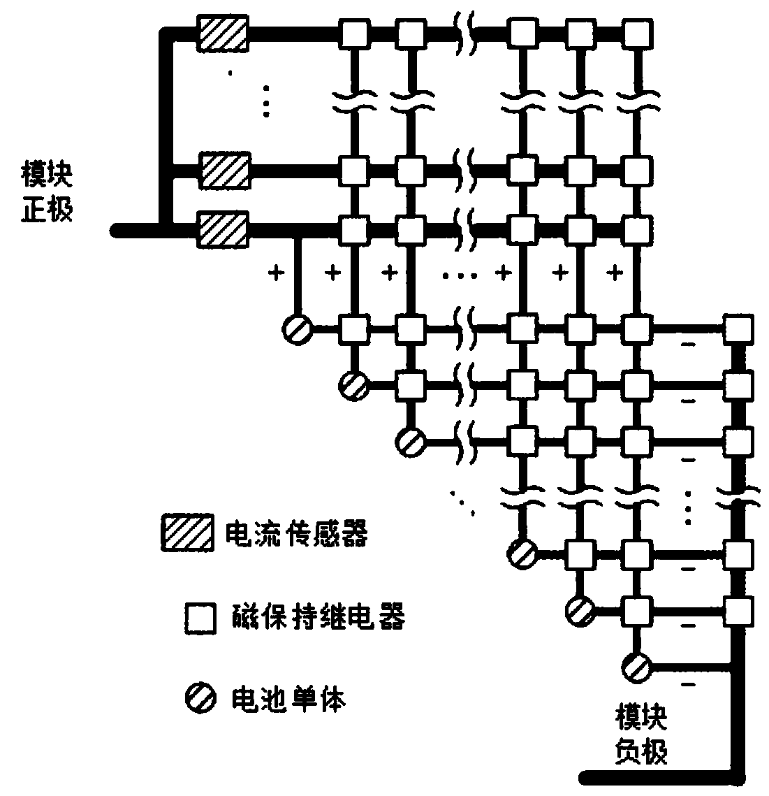
[0037] The working principle of the present invention is explained below by taking a battery module composed of 3 series and 3 parallel battery cells as an example:

[0038] Such as Figure 4 As shown, it is a dynamically reconfigurable battery energy storage system based on a battery module composed of battery cells, including a dynamically reconfigurable battery pack semi-matrix topology, a monomer reorganization system controller, a battery management system BMS, and an energy storage monitoring system EMS and current sensors.

[0039] The single recombination system controller is connected with the battery group semi-matrix topology. The battery management system BMS includes the battery management unit BMU, the battery control unit BCU and the battery master control unit BAU, the battery management unit BMU, the battery control unit BCU and the battery master control unit The unit BAU is connected through the CAN bus, the output terminal of the battery management unit BM...

Embodiment 2

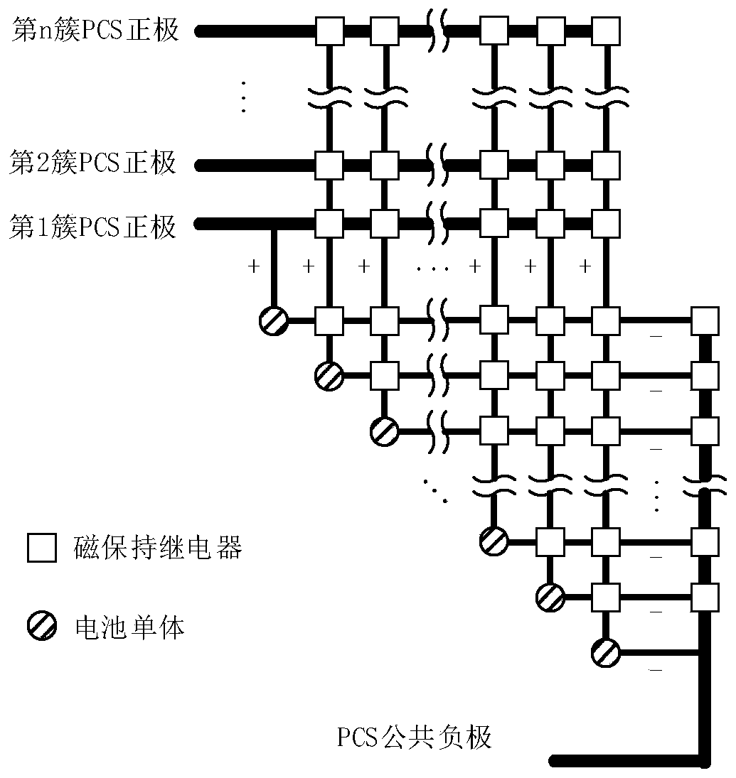
[0047] The working principle of the present invention is explained below by taking a battery stack composed of 3 series and 3 parallel battery modules as an example:

[0048] Such as Figure 9 Shown is a dynamically reconfigurable battery energy storage system based on battery modules to form a battery stack, including a dynamically reconfigurable battery pack semi-matrix topology, module reorganization system controller, battery management system BMS, energy storage monitoring system EMS and Energy storage converter PCS.

[0049] The battery pack semi-matrix topology is connected to the module reorganization system controller and the battery management system BMS respectively, the output terminal of the battery management system BMS is connected to the input terminal of the monomer recombination system controller, and the module reorganization system controller is connected to the energy storage monitoring system EMS communicate with each other.

[0050] The battery stack c...


PUM


Abstract

The invention discloses a dynamically reconfigurable battery pack semi-matrix type topological structure. An m number of battery monomers or battery modules are connected in series to form a seriallyconnected battery pack or battery cluster; an n number of serially connected battery packs or battery clusters are connected in parallel to form a battery module or battery pile; anodes and cathodes of the battery monomers or battery modules are respectively connected with anode and cathode busbars; the anode and cathode busbars of the battery monomers and main anode and cathode busbars of the battery modules form a semi-matrix type electrical structural topology, or the anode and cathode busbars of the battery modules and the main anode and cathode busbars of the battery piles form a semi-matrix type electrical structural topology; corresponding crossed positions between the various busbars are connected through switch devices; and the total number of the switch devices is 0.5m<2>n<2>+mn<2>+0.5mn-n-1. The invention also discloses a dynamically reconfigurable battery energy storage system with the semi-matrix type electrical structural topology and a dynamic reconfiguration control method. Dynamic reconfiguration of the battery monomers or battery modules is quickly realized without changing physical positions of the battery monomers or battery modules.

Description

technical field [0001] The invention relates to an electrochemical energy storage system, in particular to a dynamically reconfigurable semi-matrix topological structure of a battery pack, a system and a control method. Background technique [0002] The smart grid will be connected to a large-scale electrochemical energy storage system for frequency regulation, and the energy storage medium in these electrochemical energy storage systems mainly uses cascade utilization batteries decommissioned in electric vehicles and other fields. Battery cells or modules with similar battery status are reconstituted into battery modules, battery clusters, battery stacks, and new energy storage systems. Due to the previous production process and use environment of these step-by-step batteries may be different, there is a certain degree of difference in the battery status and physical fitness of the battery cells or modules. As the number of cycles increases, the inconsistency (discreteness)...

Claims


Application Information

Patent Timeline
IPC IPC(8): H02J7/00
CPCY02E60/10
Inventor 孙天奎袁宇波袁晓东高磊卜强生范栋琛赵玉林
Owner STATE GRID JIANGSU ELECTRIC POWER CO ELECTRIC POWER RES INST
Why Eureka
Try Eureka