

Power turning output device for internal combustion engine
A technology of power changing and output devices, which is applied in the direction of machines/engines, mechanical equipment, etc., can solve problems such as increased use cost, slippage, and large power consumption, and achieve the effect of small use space and reduced use cost
Inactive Publication Date: 2019-05-14
谢从树
View PDF0 Cites 0 Cited by
- Summary
- Abstract
- Description
- Claims
- Application Information
AI Technical Summary
Problems solved by technology
[0003] The power output device of the internal combustion engine of the present invention overcomes the fact that the power output shaft of the traditional horizontal single-cylinder diesel engine is 90° to the cylinder block, and the cylinder block plus the crankcase makes the size of the horizontal single-cylinder diesel engine too long. Agricultural machinery can only be installed vertically, so that the power of the flywheel is also driven by the belt. Because the belt drive has the defects of slipping and high friction, power consumption increases the cost of use.
Method used
View moreImage
Smart ImageViewing Examples

Examples
Embodiment 1
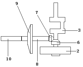
[0011] During the use of an internal combustion engine power change output device, the flywheel of the diesel engine is started to reach the rated speed, and the driving bevel gear installed on the crankshaft transmits the power of the flywheel to the driven bevel gear, and the driven bevel gear transmits the power to the driven bevel gear. The power output shaft, the power output shaft transmits power to the main shaft of the gearbox through the clutch friction plate assembly, and then transmits the power to the drive axle of agricultural machinery after speed change.
Login to View More PUM
 Abstract
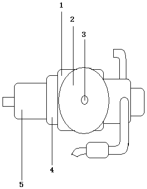
The invention provides a power turning output device for an internal combustion engine. A set of umbrella-shaped gear is additionally installed between a crankshaft of an original horizontal single-cylinder diesel and a flywheel. Power is transmitted to a power output shaft through the umbrella-shaped gear. Shaft transmission is achieved easily, non-slip friction force is small, thus power lost inthe power transmitting process is reduced, the use cost is reduced, and space used when the diesel is installed longitudinally is smaller.
Description
technical field [0001] The invention relates to a power direction-changing output device of an internal combustion engine, which belongs to the field of agricultural machinery. Background technique [0002] The power output shaft of a traditional horizontal single-cylinder diesel engine is 90° to the cylinder block. The cylinder block plus the crankcase make the size of the horizontal single-cylinder diesel engine too long. It can only be installed vertically on agricultural machinery, so the power of the flywheel is also Through the belt drive, because the belt drive has the defects of slipping and large frictional power consumption, the cost of use is increased. Contents of the invention [0003] The power output device of the internal combustion engine of the present invention overcomes the fact that the power output shaft of the traditional horizontal single-cylinder diesel engine is 90° to the cylinder block, and the cylinder block plus the crankcase makes the size of...
Claims
Login to View More Application Information
Patent Timeline
 Patent Type & AuthorityApplications(China)
IPC IPC(8): F02B61/06
Inventor谢从树谢伟
Owner谢从树