Secondary parallel heat pump unit

A technology of parallel connection of heat pump units, applied in the field of heat pumps, to achieve the effects of reducing irreversible heat transfer losses, reducing transmission and distribution energy consumption and pipeline network investment, and improving comprehensive energy utilization efficiency

Inactive Publication Date: 2019-05-14
耿艳
View PDF0 Cites 1 Cited by
  • Summary
  • Abstract
  • Description
  • Claims
  • Application Information

AI Technical Summary

Problems solved by technology

[0003] In order to overcome the shortcomings of the above-mentioned prior art, the purpose of the present invention is to provide a simple structure, when the common ground (water) source heat pump unit adopts the "large temperature difference, small flow" operation mode, the existing system coefficient of performance (COP ) is reduced and the energy utilization efficiency is reduced, and when an operation mode of "large temperature difference and small flow" is adopted on both the cold and heat source sides, the energy utilization efficiency of the unit is significantly higher than that of ordinary heat pump units. An improved two-stage parallel heat pump unit

Method used


Image

  • Secondary parallel heat pump unit
  • Secondary parallel heat pump unit

Examples


Embodiment 1

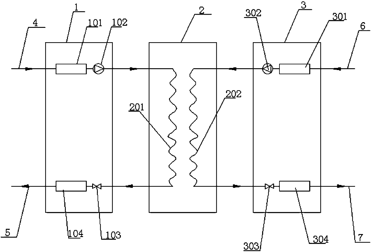
[0023] Such as figure 1 The two-stage parallel heat pump unit includes two first heat pump units 1 and second heat pump units 3 arranged in parallel, and a heat exchange is arranged between the first heat pump unit 1 and the second heat pump unit 3 Unit 2; the first heat pump unit 1 is mainly used to heat cold water, the second heat pump unit 2 is mainly used to cool down the hot water entering the second heat pump unit 2, and the heat exchange unit 2 Mainly to exchange heat between the hot water heated in the first heat pump unit and the cooled water in the second heat pump unit, which can realize gradient heating and cooling, reduce the temperature difference between the evaporator and condenser, and reduce the irreversible heat transfer loss , the overall coefficient of performance of the unit is improved.

[0024] The first heat pump unit 1 includes a first evaporator 101, a first compressor 102, a first solenoid valve 103 and a first condenser 104, and the cold water inl...

Embodiment 2

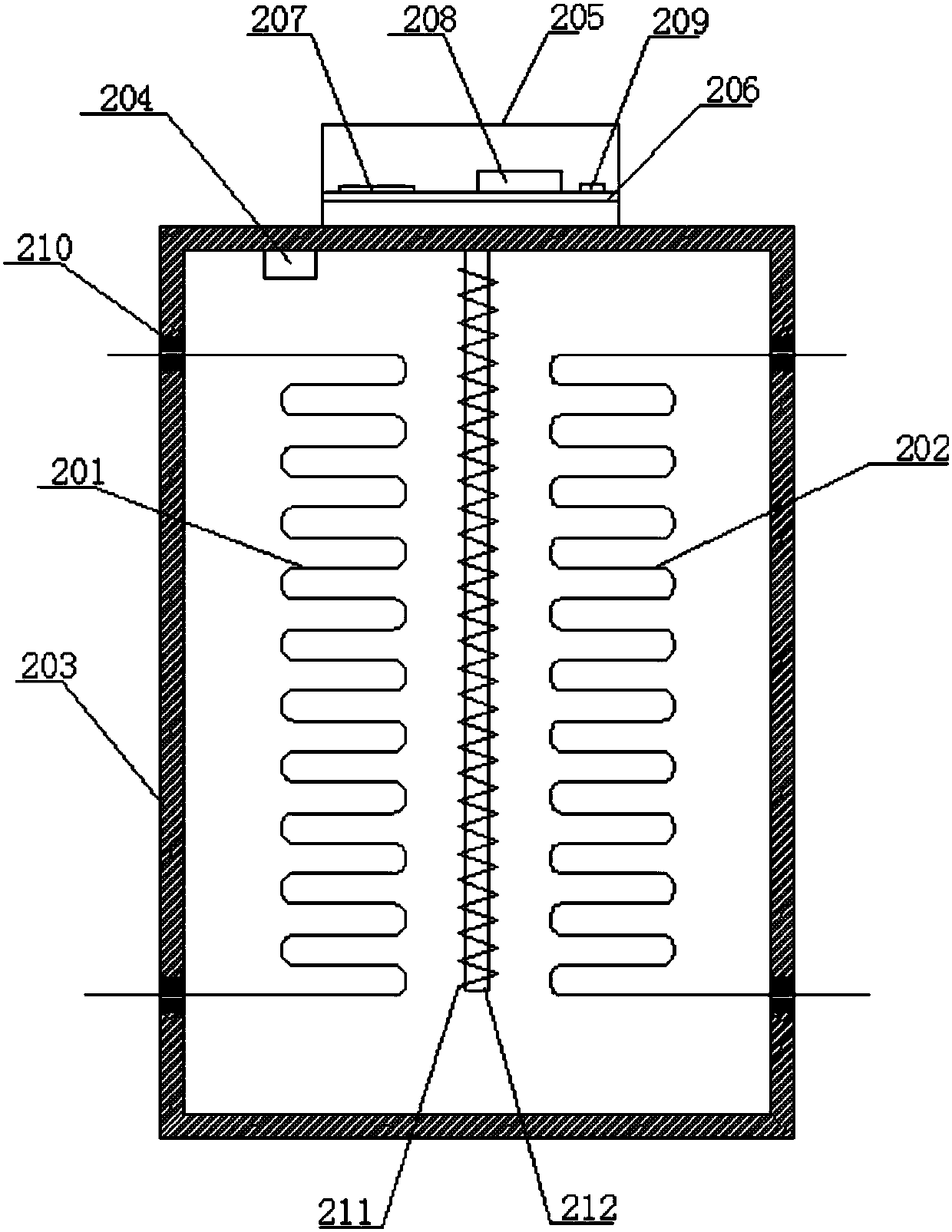
[0028] On the basis of Example 1, such as figure 2 The shown heat exchange unit 2 includes an insulated box body 203, the first heat exchange assembly 201 and the second heat exchange assembly 202 are arranged in the insulated box body 203, and the insulated box body 203 is provided with The temperature sensor 204 is electrically connected to the first solenoid valve 103 and the second solenoid valve 303 respectively. The temperature sensor 204 is used to detect the temperature in the heat preservation box 203, and control the degree of opening and closing of the first solenoid valve and the second solenoid valve through the detected temperature, for example, when the temperature is too high, control the first solenoid valve When the flow rate decreases, the flow rate of the second electromagnetic valve is controlled to increase. When the temperature is too low, the flow rate of the first electromagnetic valve is controlled to increase, and the flow rate of the second electro...

Embodiment 3

[0035] On the basis of Example 1, the first heat exchange component 201 and the second heat exchange unit 202 are both made of aluminum fins, and the finned first heat exchanger made of aluminum The thermal assembly 201 and the second heat exchange assembly 202 are arranged to cross each other. The first heat exchanging component 201 and the second heat exchanging component 202 are made of aluminum, which has higher heat exchanging performance. Fins are used for heat exchanging, which increases the heat exchanging area, and the cross setting can quickly conduct heat exchanging .


PUM


Abstract

The invention relates to a secondary parallel heat pump unit. The heat pump unit comprises the first heat pump unit and the second heat pump unit are arranged in parallel, and a heat exchange unit isarranged between the first heat pump unit and the second heat pump unit. A lower hot water step can be heated to a higher temperature in a gradient manner, the cold water is cooled in a gradient manner according to the direction opposite to the heating temperature of the hot water, the temperature difference between hot water and cold water at the inlet and outlet of the heat pump is increased, and the comprehensive energy utilization efficiency of the system is improved.

Description

technical field [0001] The invention relates to the technical field of heat pumps, and relates to a two-stage parallel heat pump unit. Background technique [0002] With the maturity of heat pump technology, various heat pump technologies using groundwater, surface water or industrial waste water as heat sources have been widely used in refrigeration, heating and hot water supply systems. The coefficient of performance of the heat pump unit is an important factor in determining the efficiency of energy utilization. The ground (water) source heat pump unit adopts the operation mode of "large temperature difference and small flow", which can greatly reduce the energy consumption of the system's transmission and distribution and the investment of the pipe network system. When the ordinary ground (water) source heat pump unit adopts the operation mode of "large temperature difference and small flow", when the inlet water temperature is constant, the temperature of the hot water...

Claims


Application Information

Patent Timeline
IPC IPC(8): F24H4/02F25B30/02
Inventor 耿艳
Owner 耿艳
Why Eureka
Try Eureka