
Concentration device and pneumatic focusing system

A technology of concentrating device and focusing system, applied in the preparation of test samples, etc., can solve the problems of loss of large particles, large load of vacuum pump, increase of temperature rise, etc., to increase transmission efficiency and throughput rate, and increase sample flow rate. , the effect of improving focusing ability

Pending Publication Date: 2019-05-14
GUANGZHOU HEXIN INSTR CO LTD
View PDF0 Cites 4 Cited by
  • Summary
  • Abstract
  • Description
  • Claims
  • Application Information

AI Technical Summary

Problems solved by technology

[0003] Among them, for the conventional aerodynamic focusing system, the flow-restricting hole with a diameter of about 0.1mm is used, so that the sampling flow rate of the device is usually limited to 100mL / min, the flux of particles per unit time is low, and the collection of particles The efficiency is low, and at the same time, a large amount of large particles (diameter ≥ 3 μm) will be lost near the flow-restricting hole, resulting in a low pass rate of large particles
In this regard, if the diameter of the flow-limiting hole is increased, the load of the vacuum pump corresponding to the vacuum chamber downstream of the pneumatic focusing system will be too large, and the temperature rise will increase sharply

Method used


Image

  • Concentration device and pneumatic focusing system
  • Concentration device and pneumatic focusing system

Examples


Embodiment Construction

[0030] In order to facilitate the understanding of the present invention, the present invention will be described more fully below with reference to the associated drawings. Preferred embodiments of the invention are shown in the accompanying drawings. However, the present invention can be embodied in many different forms and is not limited to the embodiments described herein. On the contrary, these embodiments are provided to make the understanding of the disclosure of the present invention more thorough and comprehensive.

[0031] It should be noted that when an element is referred to as being “fixed” to another element, it can be directly on the other element or there can also be an intervening element. When an element is referred to as being "connected to" another element, it can be directly connected to the other element or intervening elements may also be present.

[0032] Unless otherwise defined, all technical and scientific terms used herein have the same meaning as...


PUM


Abstract

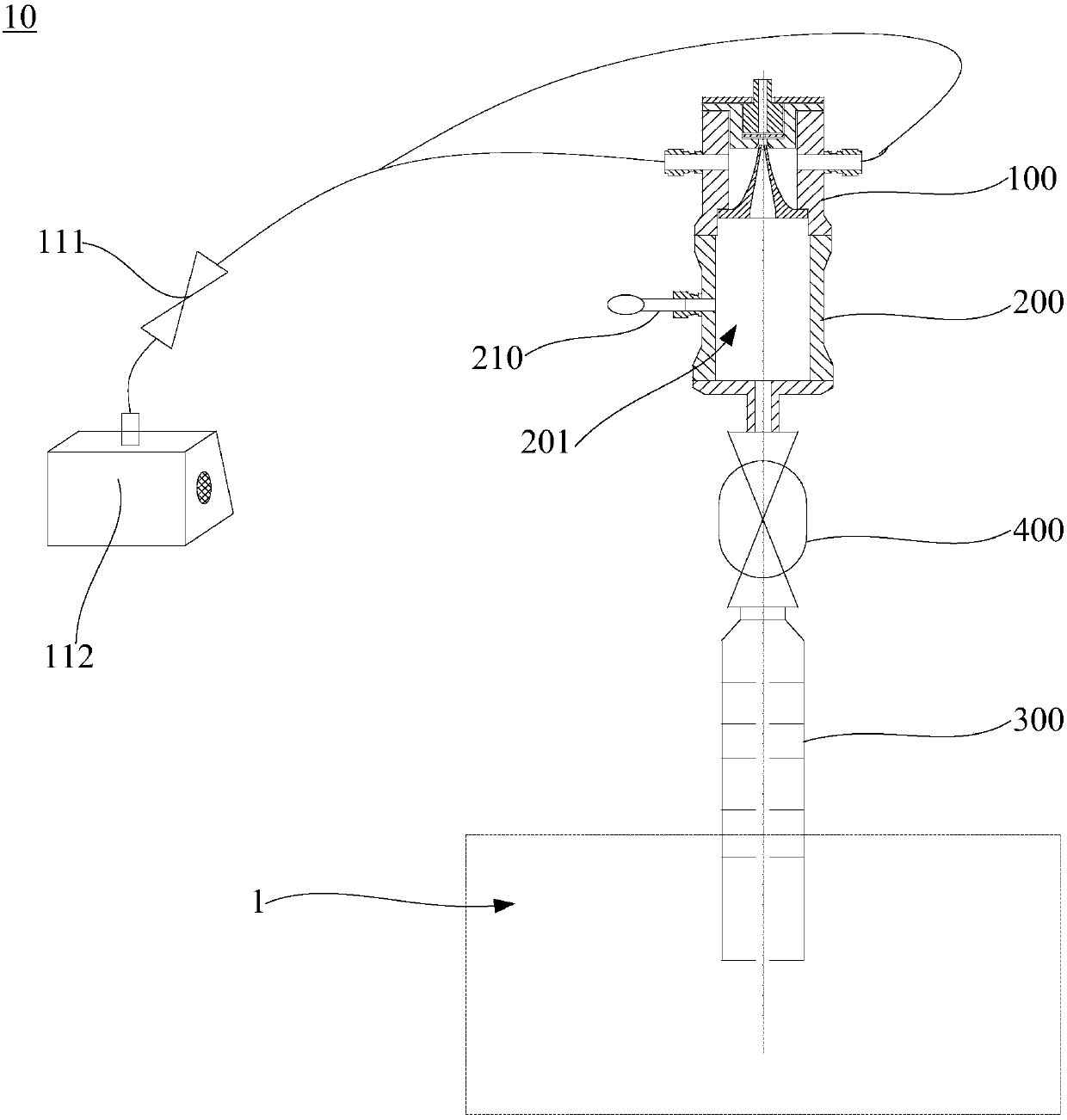
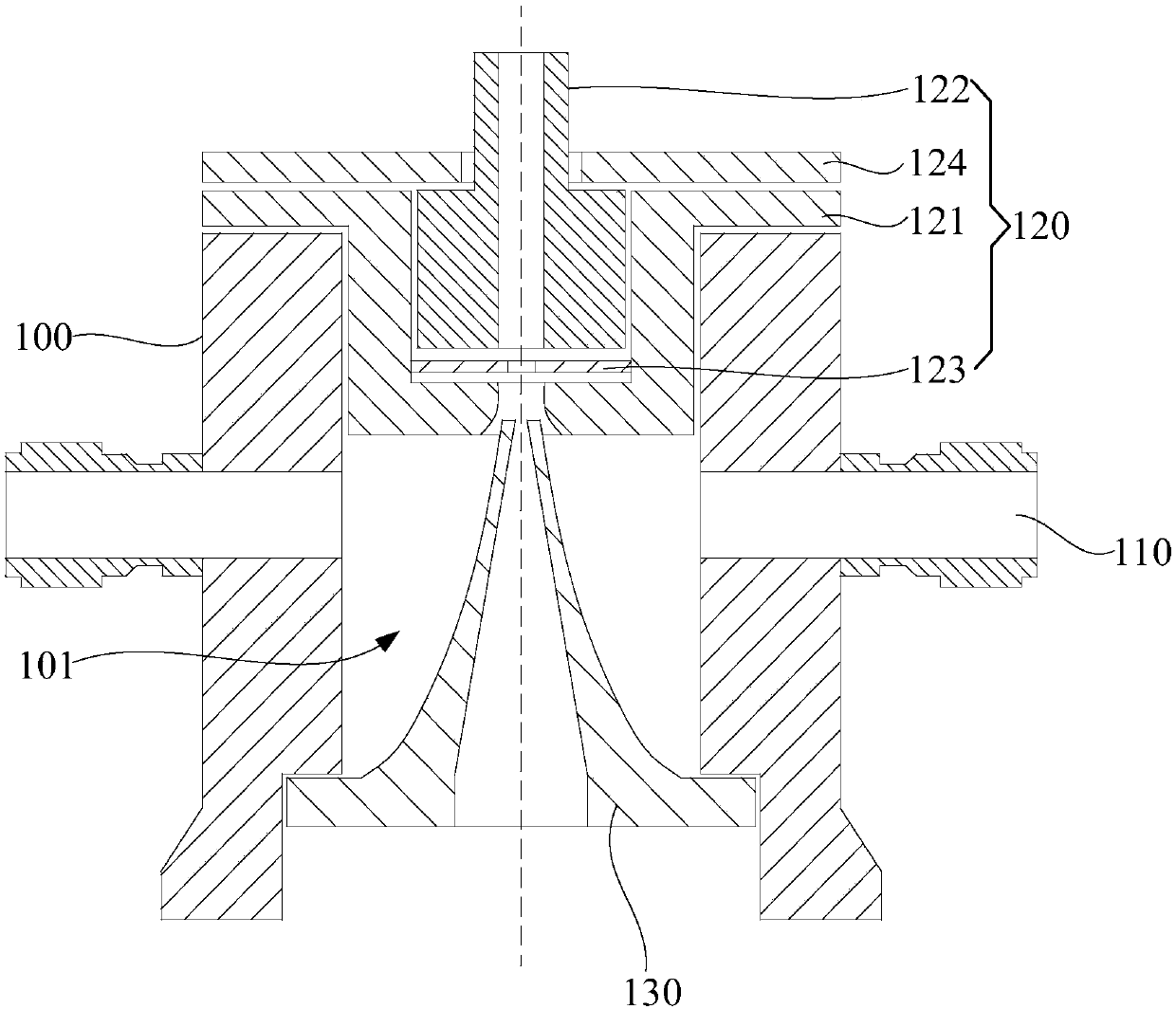
The invention relates to a concentration container and a pneumatic focusing system containing the concentration container. The concentration device comprises the concentration container, a sample introduction mechanism, a stream guidance mechanism and a buffer container, wherein the concentration container is provided with a pneumatic cavity and an air exhaust column; the sample introduction mechanism is provided with a sample introduction channel, a current limiting hole and a shunting hole, wherein the sample introduction channel, the current limiting hole and the shunting hole are communicated in sequence; the stream guidance mechanism is arranged on the concentration container; the buffer container and the concentration container and / or the stream guidance mechanism are connected; anda stream guidance channel and a buffer cavity are communicated to meet a situation that the vacuum load requirement of vacuum analysis equipment is not affected. When the above concentration device is connected with the sample introduction joint of an aerodynamics lens, under a condition that a conventional vacuum load is adopted, under the driving of an air pressure difference, an aerosol sampleintroduction flow can be enlarged, the through rate of large-grain-size particulate matters can be greatly increased, and aerosol concentration and particulate beam focusing can be realized so as tobe favorable for carrying out aerosol sample introduction and detection under low concentration.

Description

technical field [0001] The invention relates to the field of analysis and detection equipment, in particular to a concentration device and a pneumatic focusing system. Background technique [0002] The generation of particle beams is an important technical problem in the field of atmospheric particulate matter research. The main function of the particle beam generating device is to gather the suspended particles into a particle beam of approximately single particle arrangement, and deliver it to the designated vacuum area. Generally used particle beam generating devices generally use a small flow-limiting hole (also called a "critical hole") to inject samples. The diameter of the small flow-limiting hole is about 0.1 mm, and its main function is to isolate the atmosphere from the vacuum and limit the flow rate of the sample. . Controlling the operating pressure of the particle beam generating device. The particles entering the flow-restricting aperture are generally focuse...

Claims


Application Information

Patent Timeline
IPC IPC(8): G01N1/28G01N1/40
Inventor 杜绪兵代新喻佳俊
Owner GUANGZHOU HEXIN INSTR CO LTD
Learn More