Nuclear magnetic resonance in-situ battery test accessories and test method thereof

A nuclear magnetic resonance and in-situ testing technology, which is applied in the fields of magnetic resonance measurement, secondary battery manufacturing, and magnetic variable measurement, can solve the problems of complex in-situ battery structure, inability to truly reflect battery structural changes, and large battery devices. Achieve improved electrochemical performance, simple structure, good sealing effect

Active Publication Date: 2019-05-14
DALIAN INST OF CHEM PHYSICS CHINESE ACAD OF SCI
View PDF7 Cites 5 Cited by
  • Summary
  • Abstract
  • Description
  • Claims
  • Application Information

AI Technical Summary

Problems solved by technology

[0003] At present, a large number of studies have used NMR methods to characterize the positive electrode materials, negative electrode materials and electrolytes of batteries to study the structural properties of these materials. At the same time, in-situ NMR studies have also been carried out on battery materials at different charge and discharge stages, but these studies are not It is carried out under ex-situ conditions and cannot truly reflect the structural changes during charging and discharging in the battery
Due to the complexity and limitations of the NMR spectrometer itself, it is necessary to develop a battery device with a special structure to study the charging and discharging process of the battery. Most of the existing in-situ battery devices are used in X-ray diffraction and spectral analysis. and other fields, and most of these in situ batteries have complex structures and battery devices are too large to be directly applied to NMR methods

Method used


Image

  • Nuclear magnetic resonance in-situ battery test accessories and test method thereof
  • Nuclear magnetic resonance in-situ battery test accessories and test method thereof
  • Nuclear magnetic resonance in-situ battery test accessories and test method thereof

Examples


Embodiment 1

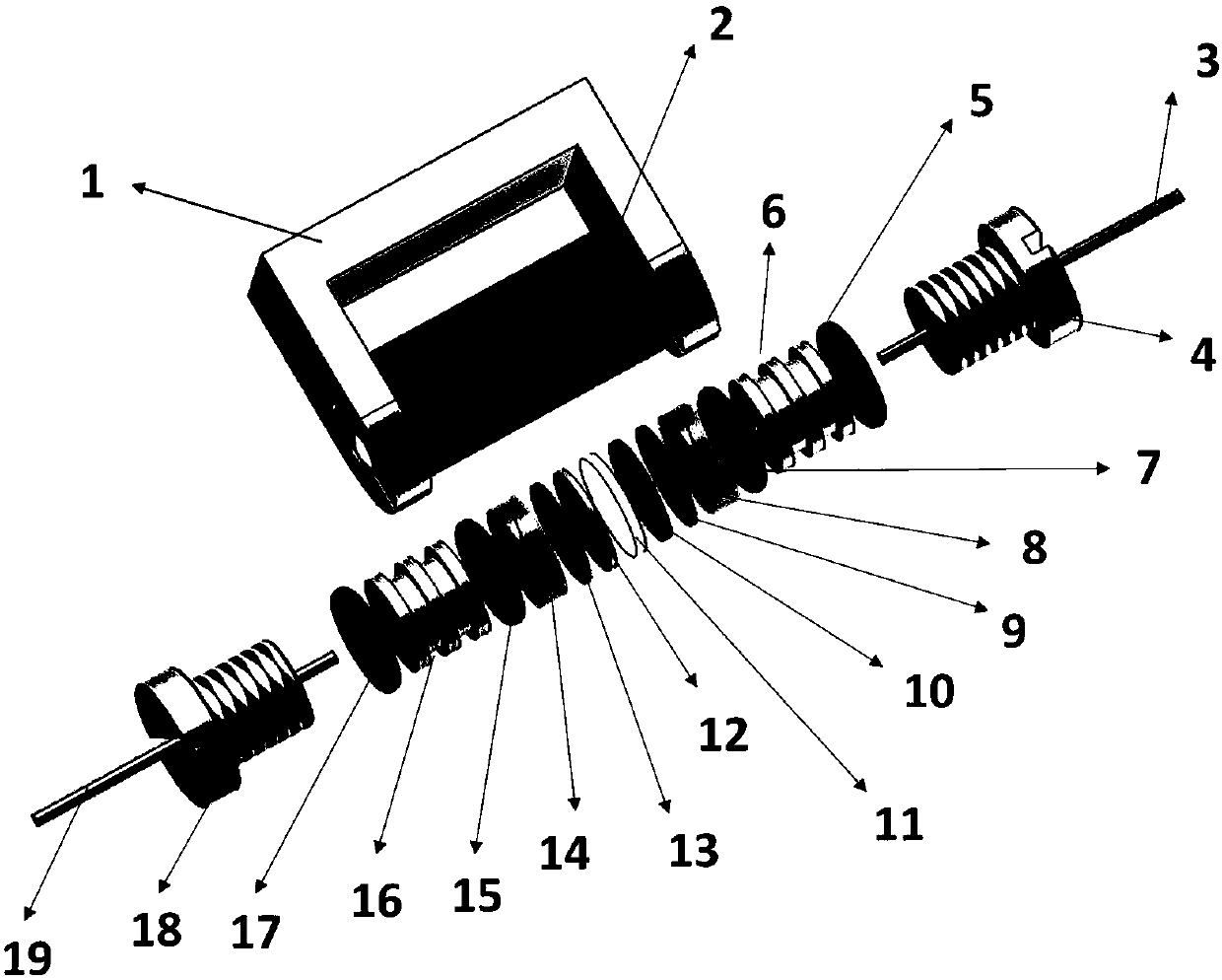
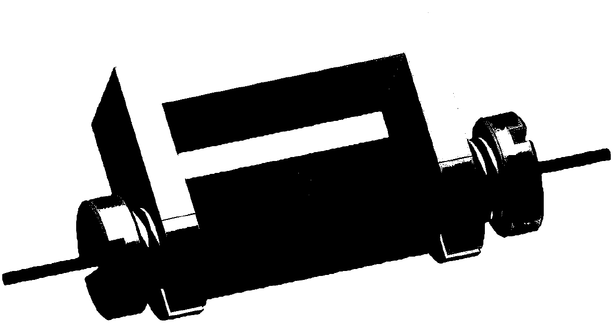
[0048] figure 1 A schematic diagram of the NMR in situ cell attachment. The in-situ battery was used to observe the in-situ dynamic changes of the lithium-sulfur battery during charge and discharge. Specifically include the following:

[0049] Selection and assembly of in-situ battery materials:

[0050] The battery cylindrical shell 2 is fixed on the battery holder 1 through the first and second pressurized nuts;

[0051] Between the first pressurizing nut 4 and the second pressurizing nut 8, the inside of the battery cylindrical casing 2 is sequentially provided with a first fixed platform 6, a first sealing insulating pad 8, a first current collector 9, and a positive electrode sheet 10. , a diaphragm 11, a negative electrode sheet 12, a second current collector 13, a second sealing insulating pad 14, and a second fixing platform 16, each fixing platform is provided with two sealing rings.

[0052] Use quartz glass battery cylinder shell 2, about 20mm high, 10mm outer d...


PUM


Abstract

The invention relates to nuclear magnetic resonance in-situ battery test accessories, which comprise a battery fixing frame, a cylindrical shell, a tension nut, a first fixing cover with a central through hole, a first sealing ring, a second sealing ring, a first insulation sealing gasket, a first current collector, a positive electrode plate, a diaphragm, a negative electrode plate, a second current collector, a second insulation sealing gasket, a third sealing ring, a fourth sealing ring and a second fixing cover containing a central through hole. The device is simple and the sealing performance is good, and meanwhile, the loading and unloading operations are simple and convenient, and in-situ on-line detection of a battery in a nuclear magnetic resonance spectrometer can be efficientlyrealized. The invention further discloses a test method for in-situ detection of battery charging and discharging processes by using the nuclear magnetic resonance spectrometer.

Description

technical field [0001] The invention designs the field of batteries, specifically a battery for in-situ detection by using nuclear magnetic resonance, and realizes in-situ on-line detection of battery charging and discharging reactions. Background technique [0002] In recent years, with the development of technology, various advanced batteries such as lithium-ion batteries, lithium-sulfur batteries, lithium-air batteries, and sodium-ion batteries have been widely used in various electronic products, including electric vehicles, mobile phones, computers, wireless Man-machine and so on. At the same time, people have higher and higher requirements for the performance of these products such as long battery life and fast response, which poses greater challenges to battery capacity, cycle stability and other performance. Therefore, a deep understanding of the charge-discharge reaction process in batteries is particularly important for improving battery performance. Nuclear magn...

Claims


Application Information

Patent Timeline
Patent Type & Authority Applications(China)
IPC IPC(8): G01R31/364G01R31/385G01R33/44H01M10/04
CPCY02E60/10Y02P70/50
Inventor 包信和倪效刘宪春韩秀文
Owner DALIAN INST OF CHEM PHYSICS CHINESE ACAD OF SCI
Why Eureka
Try Eureka