Image pickup lens and electronic equipment
A camera lens and lens technology, which is applied in the field of electronic equipment and camera lenses, can solve problems such as unsatisfactory photography systems, and achieve the effect of meeting application requirements, large aperture, and high pixels
- Summary
- Abstract
- Description
- Claims
- Application Information
AI Technical Summary
Problems solved by technology
Method used
Image

Examples
Embodiment 1
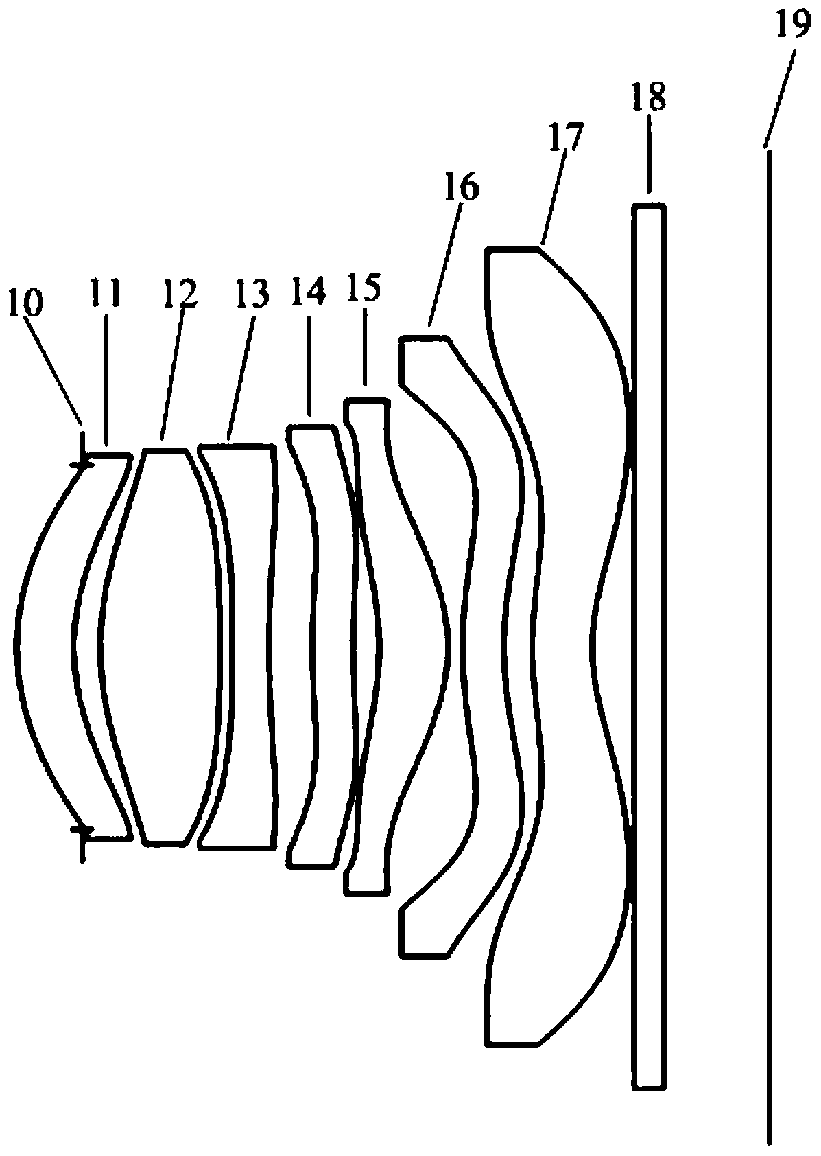
[0068] Please refer to figure 1 , shows a schematic structural diagram of the imaging lens of Embodiment 1. As can be seen from the figure, the imaging lens of this embodiment includes a diaphragm 10, a first lens 11, a second lens 12, a third lens 13, a fourth lens 14, a fifth lens 15, Each of the sixth lens 16 and the seventh lens 17 has an object side facing the object side and an image side facing the image side, and the object side and the image side of each lens are aspherical. The first lens 11 has positive refractive power, its object side is convex at the near optical axis, and its image side is concave at the near optical axis. The second lens 12 has positive refractive power, its object side is convex at the near optical axis, and its image side is convex at the near optical axis. The third lens 13 has negative refractive power, its object side is concave at the near optical axis, and its image side is concave at the near optical axis. The fourth lens 14 has posi...
Embodiment 2
[0081] Please refer to Figure 4 , shows a schematic structural diagram of the imaging lens of Embodiment 2. As can be seen from the figure, the imaging lens of this embodiment includes a diaphragm 20, a first lens 21, a second lens 22, a third lens 23, a fourth lens 24, a fifth lens 25, Each of the sixth lens 26 and the seventh lens 27 has an object side facing the object side and an image side facing the image side, and the object side and the image side of each lens are aspherical. The first lens 21 has positive refractive power, its object side is convex at the near optical axis, and its image side is concave at the near optical axis. The second lens 22 has positive refractive power, its object side is convex at the near optical axis, and its image side is convex at the near optical axis. The third lens 23 has negative refractive power, its object side is concave at the near optical axis, and its image side is concave at the near optical axis. The fourth lens 24 has pos...
Embodiment 3
[0091] Please refer to Figure 7 , shows a schematic structural diagram of the imaging lens of Embodiment 3. As can be seen from the figure, the imaging lens of this embodiment includes a diaphragm 30, a first lens 31, a second lens 32, a third lens 33, a fourth lens 34, a fifth lens 35, Each of the sixth lens 36 and the seventh lens 37 has an object side facing the object side and an image side facing the image side, and the object side and the image side of each lens are aspherical. The first lens 31 has negative refractive power, its object side is convex at the near optical axis, and its image side is concave at the near optical axis. The second lens 32 has positive refractive power, its object side is convex at the near optical axis, and its image side is convex at the near optical axis. The third lens 33 has negative refractive power, its object side is concave at the near optical axis, and its image side is concave at the near optical axis. The fourth lens 34 has pos...
PUM
 Abstract
Description
Claims
Application Information
 - Generate Ideas
- Intellectual Property
- Life Sciences
- Materials
- Tech Scout
- Unparalleled Data Quality
- Higher Quality Content
- 60% Fewer Hallucinations
Browse by: Latest US Patents, China's latest patents, Technical Efficacy Thesaurus, Application Domain, Technology Topic, Popular Technical Reports.
© 2025 PatSnap. All rights reserved.Legal|Privacy policy|Modern Slavery Act Transparency Statement|Sitemap|About US| Contact US: help@patsnap.com