Novel insulation tube type bus of 35kv and below, and manufacture technology thereof

A production process and technology of insulating tubes, which are applied in the directions of insulating cables, insulating conductors, and insulating conductors/cables, etc., can solve the problems of insufficient uniform structure, difficult to meet the requirements of cables, unsuitable for waterproofing and narrowness, etc., and reduce construction costs. The effect of difficulty, reduction of joints, and convenient construction

Pending Publication Date: 2019-05-17
北京中良恒通科技有限公司
View PDF0 Cites 2 Cited by
  • Summary
  • Abstract
  • Description
  • Claims
  • Application Information

AI Technical Summary

Problems solved by technology

[0004] 1. Traditional overhead busbars (including tubular and rectangular): they are insulated by air and are only suitable for large-spacing layout and require insulator support. They are not suitable for waterproof and narrow occasions that require dense and compact layout;
[0005] 2 Composite insulating tubular busbar: the use of insulating structure greatly broadens the application occasions, but it adopts a capacitive screen structure composed of wrapping inner and outer shielding, insulating film and semi-conductive paper, the structure is not uniform enough, and the failure rate is high; traditional wall-through Casing has a similar problem;
[0006] 3 Conventional ordinary cables: it can solve the problem of large length, large span, waterproof, etc., but when the current carrying capacity is super large, it is difficult for traditional cables to meet the requirements, and it is difficult to lay when encountering a small bending radius

Method used


Image

  • Novel insulation tube type bus of 35kv and below, and manufacture technology thereof
  • Novel insulation tube type bus of 35kv and below, and manufacture technology thereof

Examples


Embodiment Construction

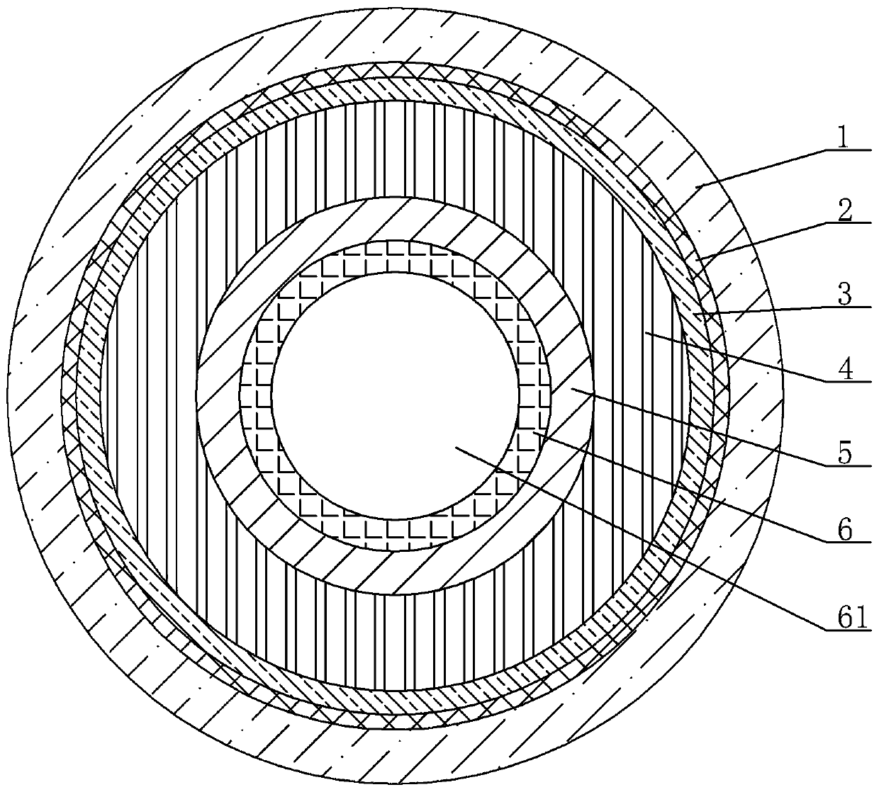
[0028] A new type of insulated tubular busbar of 35kv and below, see figure 1 : It includes an outer sheath 1, a metal shielding layer 2, an outer shielding layer 3, an insulating layer 4, an inner shielding layer 5, a tubular copper conductor 6, and a tubular copper conductor, which are arranged in sequence from the outside to the inside. The center of 6 is a cavity structure 61, the outer ring surface of the tubular copper conductor 6 is covered with an inner shielding layer 5, the outer ring surface of the inner shielding layer 5 is covered with an insulating layer 4, and the outer ring surface of the insulating layer 4 is covered There is an outer shielding layer 3 , the outer ring surface of the outer shielding layer 3 is covered with a metal shielding layer 2 , and the outer ring surface of the metal shielding layer 2 is covered with an outer sheath 1 .

[0029] The tubular copper conductor 6 is specifically a high-conductivity copper tube, and the cross-sectional area o...


PUM


Abstract

The invention provides a novel insulation tube type bus of 35kv and below. The reliability of an insulation bus is improved, and the bus has the advantages of being convenient in construction, free from maintenance and wide in applicable range. The bus can be subjected to large-length delivery, joints are greatly reduced, so that a fault opportunity is reduced, construction difficulty is lowered,and cost is lowered. The bus comprises an outer sheath of which the cross section is of a circular ring shape, a metal shielding layer, an outer shielding layer, an insulation layer, an inner shielding layer and a tube type copper conductor, wherein the outer sheath, the metal shielding layer, the outer shielding layer, the insulation layer, the inner shielding layer and the tube type copper conductor are arranged in sequence from outside to inside; the center of the tube type copper conductor is of a cavity structure; the outer ring surface of the tube type copper conductor is coated with theinner shielding layer; the outer ring surface of the inner shielding layer is coated with the insulation layer; the outer ring surface of the insulation layer is coated with an outer shielding layer;the outer ring surface of the outer shielding layer is coated with the metal shielding layer; and the outer ring surface of the metal shielding layer is coated with the outer sheath. The invention also provides a manufacture technology for the insulation tube type bus.

Description

technical field [0001] The invention relates to the technical field of power transmission busbar structure, specifically a new type of insulating tubular busbar of 35kV or below, and the invention also provides a manufacturing process of the insulating tubular busbar. Background technique [0002] At present, traditional overhead busbars, composite insulated tubular busbars (semi-insulated, fully insulated), and cables in the general sense are generally used as the busbars for the high-power output terminals of 35kV and below substations, as the connection between the output terminal and the switch and control part in the power station . If it is necessary to pass through the wall, a special wall casing should be used. [0003] Limitations of these traditional busbars: [0004] 1. Traditional overhead busbars (including tubular and rectangular): they are insulated by air and are only suitable for large-spacing layout and require insulator support. They are not suitable for...

Claims


Application Information

Patent Timeline
Patent Type & Authority Applications(China)
IPC IPC(8): H01B9/00H01B9/02H01B7/00H01B7/02H01B7/17H01B13/14H01B13/22H01B13/24H01B13/34
Inventor 张翼翔周健
Owner 北京中良恒通科技有限公司
Why Eureka
Try Eureka