Integrated composite progressive forming device and process of large shell branch pipe flange

A branch pipe flange, incremental forming technology, applied in the field of plastic forming, can solve the problems of cumbersome clamping process, uneven force on the cylinder, difficult control, etc., to achieve high flexibility of forming process, improve forming efficiency, and clamping process simple effect

Active Publication Date: 2019-05-21
XI AN JIAOTONG UNIV
View PDF8 Cites 2 Cited by
  • Summary
  • Abstract
  • Description
  • Claims
  • Application Information

AI Technical Summary

Problems solved by technology

The specific process is to pre-open an elliptical hole on the parent body of the GIS shell, and then press and flanging to form a branch pipe. The quality of the straight edge of this method is not high, and cracks are prone to occur at the edge of the hole flange, and the flange is often not covered with a film, which requires manual work in the later stage. For mold repair, for branch pipes of different sizes, it is necessary to manufacture corresponding stamping dies, which is costly and takes a long time, and the stamping dies are large in size, requiring corresponding auxiliary feeding mechanisms. The clamping process is cumbersome and difficult to control
The Chinese patent (application number CN201810130058.6) proposes a progressively flexible flanging device and process for a large-diameter thick-walled cylinder. This structure and process can realize the flexible forming of branch pipes, but the formed branch pipes still need to be welded on the flange. On the branch pipe, the weld seam is formed, only one tool head moves during the forming process, the forming efficiency is low, and the single tool head will cause uneven force on the cylinder, which will affect the forming quality
Chinese patent (Application No. CN201810130059.0) proposes a positive and negative compound incremental forming liner integral flange device and process, which is aimed at the flanging and flaring of flat plates, and the force characteristics of cylindrical parts are exactly the same as those of plates Different, in this patent, the lining ring is formed into a whole with the pressure plate of the heat exchanger after forming, and the structure of the lower backing plate is only suitable for flat plate forming. The flaring end of the tool head is hemispherical, and the radius is the same as that of the cylindrical part. The cylindrical part is easy to contact with the material during the forming process of the shaped part, so its device and process cannot be applied to the integrated forming of the branch pipe flange of the cylindrical part, and there is only one tool head in the forming process, the forming efficiency is low, and the force is uneven

Method used


Image

  • Integrated composite progressive forming device and process of large shell branch pipe flange
  • Integrated composite progressive forming device and process of large shell branch pipe flange
  • Integrated composite progressive forming device and process of large shell branch pipe flange

Examples


Embodiment 1

[0036] Embodiment 1, this embodiment adopts 1 pair of tool heads to form.

[0037] An integrated composite incremental forming device for branch pipe flanges of large shells, including a frame, a workbench and a symmetrical tool head system, the workbench is installed on the frame, and the symmetrical tool head system is connected to the workbench;

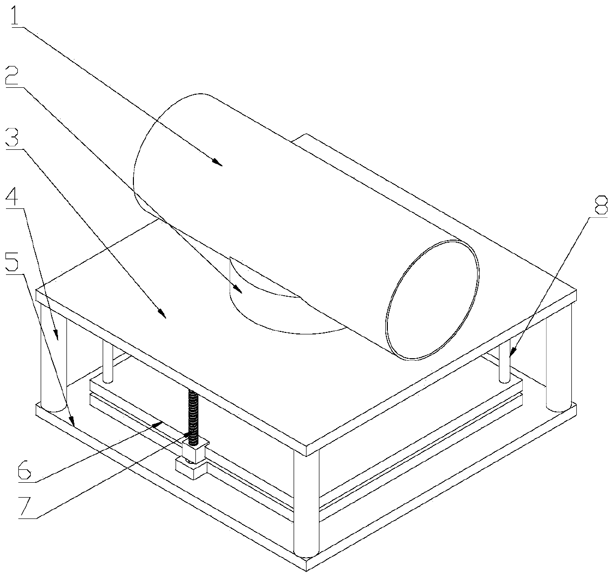
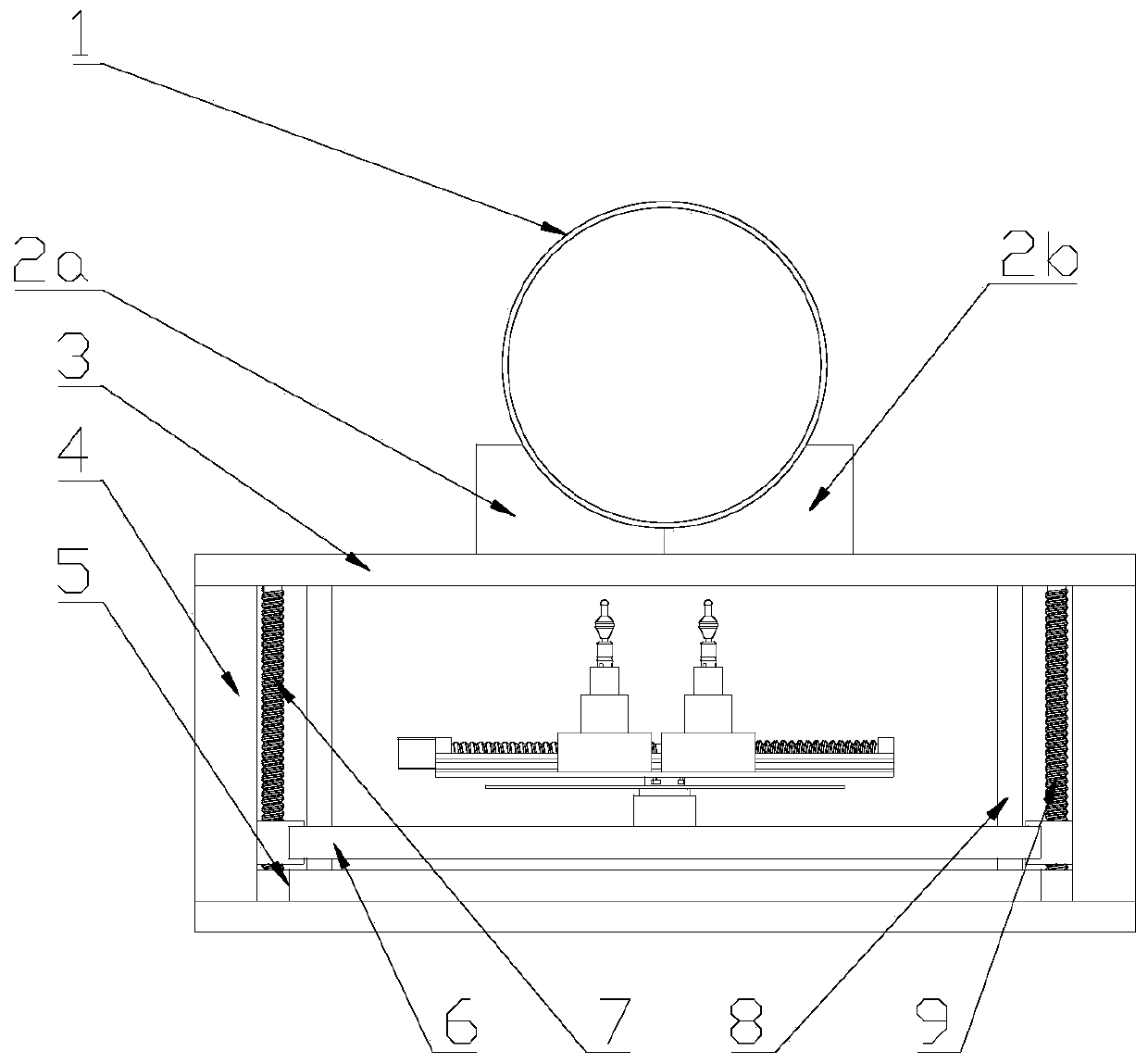
[0038] refer to figure 1 , figure 2 , Figure 7 , the frame includes a lower base 5, an upper base 3 is supported by a column 4 on the lower base 5, a die 2 is provided on the upper base 3, a cylinder 1 is supported on the die 2, and an oval hole is opened on the cylinder 1 Cooperate with die 2;

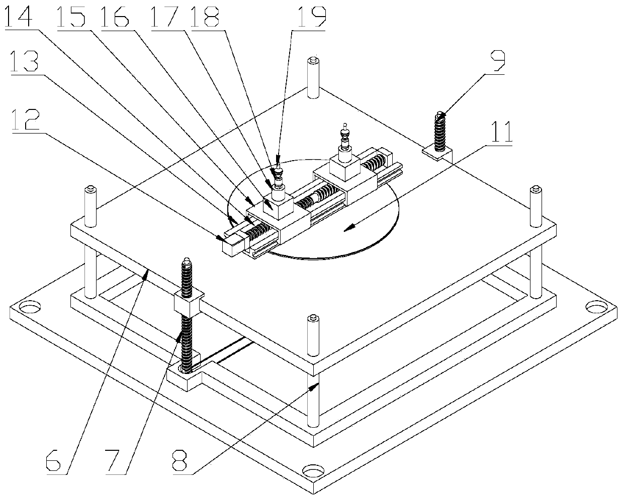
[0039] refer to figure 2 , image 3 , Figure 5, a workbench is installed between the upper base 3 and the lower base 5, the workbench includes a Z-axis mobile platform 6 connected to four guide columns 8, and the two ends of the four guide columns 8 are fixed on the lower base 5 and the upper base 3 , the Z-axis mobile platform...

Embodiment 2

[0053] Embodiment 2, with reference to Image 6 In this embodiment, the symmetrical tool head system adopts 2 pairs of tool heads to form, and the guide rails of the 2 pairs of tool heads are staggered in the vertical direction, and all the tool heads are distributed symmetrically around the axis of the turntable 11, and they are all on the same horizontal plane. Other structures and implementations Example 1 is the same.

[0054] An integrated composite incremental forming process for branch pipe flanges of large shells, using 2 pairs of tool heads, including the following steps:

[0055] 1) Refer to figure 1 , figure 2 , support the cylindrical part 1 with an oval hole on the die 2 composed of the first half die 2a and the second half die 2b, the axes of the prefabricated hole of the cylindrical part 1, the die 2, and the turntable 11 coincide ;

[0056] 2) Refer to Figure 9 a. Move all the tool heads so that the conical surface of the flanging part of the tool head i...


PUM


Abstract

The invention discloses an integrated composite progressive forming device and process of a large shell branch pipe flange. The integrated composite progressive forming device comprises a rack, a workbench and a symmetrical tool head system, wherein the workbench is arranged on the rack, and the symmetrical tool head system is connected to the workbench. According to the process, the synchronous movement of a plurality of pairs of tool heads is realized through the symmetrical tool head system, and the integrated forming of a cylindrical part branch pipe flange is realized. The forming processis high in flexibility, suitable for the integrated forming of thick-wall cylindrical part branch pipes with different sizes, and good in universality. Stamping dies and auxiliary feeding mechanismsdo not need to be manufactured, so that the cost is saved. The clamping process is simpler. The forming efficiency can be effectively improved through a multi-point symmetric structure. The stress ofa cylindrical part in the forming process is better balanced. The forming quality is high. Meanwhile, the forming efficiency is effectively improved by the plurality of pairs of tool heads.

Description

technical field [0001] The invention belongs to the technical field of plastic forming, and in particular relates to an integrated composite progressive forming device and process for branch pipe flanges of large-scale shells. Background technique [0002] Gas-insulated metal-enclosed switchgear (GIS) plays an extremely important role in current domestic and foreign power systems. The GIS shell uses sulfur hexafluoride as the insulating and arc-extinguishing medium, and its high-voltage live parts are enclosed in a metal shell, and its side walls must have branch pipe flanges for the required pipeline connection. For the GIS shell, its tightness requirements are very high, and the welding seam should be avoided as much as possible in the process of manufacturing the shell. If a saddle-shaped opening is used for welding flanges, sharp corners and burrs on the weld seam will be formed, causing electric field Concentration, partial discharge occurs, which reduces the performan...

Claims


Application Information

Patent Timeline
Patent Type & Authority Applications(China)
IPC IPC(8): B21D19/04B21D41/02
Inventor 张大伟田冲施天琳赵升吨
Owner XI AN JIAOTONG UNIV
Why Eureka
Try Eureka