Anti-sedimentation magnetorheological damper based on online monitoring
What is Al technical title?
Al technical title is built by PatSnap Al team. It summarizes the technical point description of the patent document.
A magnetorheological damper and anti-settling technology, applied in shock absorbers, shock absorbers, springs/shock absorbers, etc. subsidence effect
Active Publication Date: 2019-05-21
CHONGQING UNIV
View PDF6 Cites 6 Cited by
Summary
Abstract
Description
Claims
Application Information
AI Technical Summary
This helps you quickly interpret patents by identifying the three key elements:
Problems solved by technology
Method used
Benefits of technology
Problems solved by technology
This method can better determine the sedimentation state from the magnetorheological fluid surface to the bottom, but it cannot be applied to the interior of devices such as magnetorheological dampers
Method used
Image
Click on the blue label to locate the original text in one second.
Reading with bidirectional positioning of images and text.
Examples
Embodiment 1
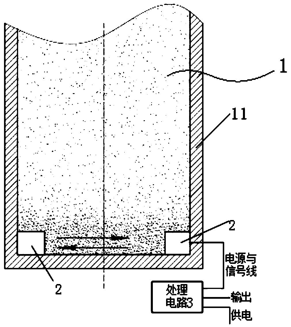
[0043] see figure 1 and figure 2 , an anti-settling magnetorheological damper based on online monitoring, mainly includes a magnetorheological damper 1, an ultrasonic transducer 2 and a processing circuit 3.
[0044] The magneto-rheological damper 1 includes a working cylinder 11 and a motor for realizing dispersion of the magneto-rheological fluid. Magnetorheological fluid is housed in the working cylinder 11 .
[0045] The magnetorheological damper 1 drives the motor to disperse the magnetorheological fluid after receiving the electrical excitation signal from the processing circuit 3 .
[0046] The ultrasonic transducer 2 is attached to the side wall at the bottom of the working cylinder 11 .
[0047] The wiring harness 21 of the ultrasonic transducer 2 extends out of the magneto-rheological damper 1 and is connected to the processing circuit 3 .
[0048] The magnetorheological fluid settles at the bottom of the cylinder so that the dispersed phase has the highest volu...
Embodiment 2
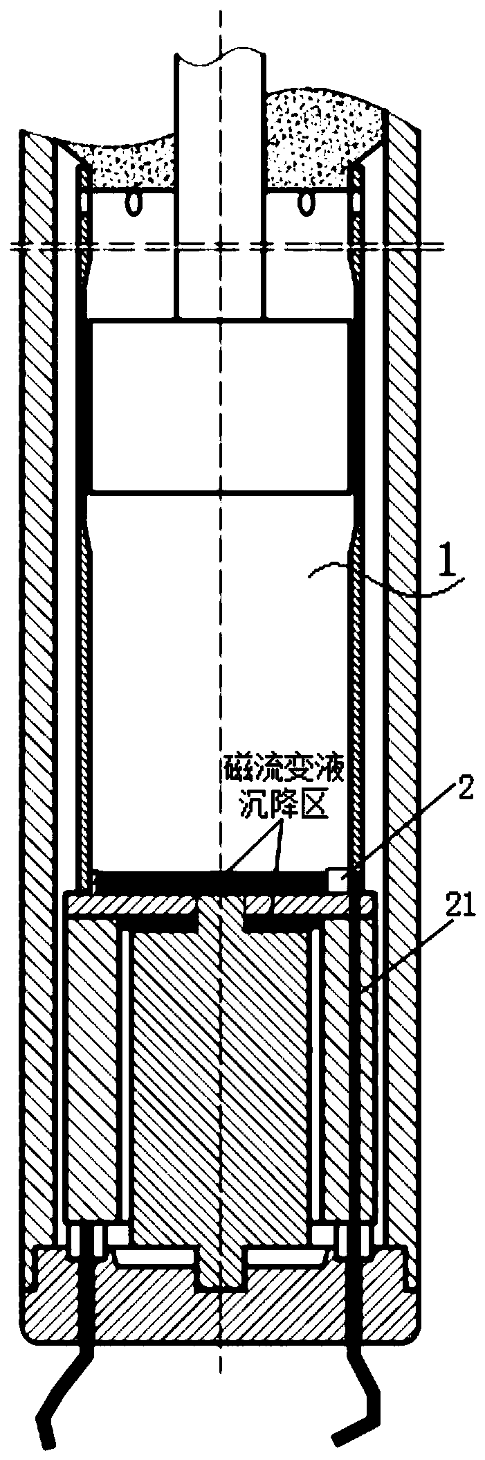
[0073] see Figure 6 to Figure 11 , The magnetorheological damper 1 mainly includes a working cylinder 11, a liquid cylinder 12, a bottom cover 13, a top cover 17, a piston assembly 18, a piston rod 19 and a motor. The motor includes a positioning column 14 , a rotor 15 and a stator 16 .
[0074] The liquid cylinder 12 is a hollow cylinder, and the opening at its lower end has threads.
[0075] The liquid cylinder 12 and the bottom cover 13 are sealed by an O-ring.
[0076] The upper end of the bottom cover 13 is a ring I131. The outer wall of the ring I131 has threads. The lower end of the bottom cover 13 is a disk I132. A circular hole I1321 is formed at the center of the end surface of the disc I132. The end surface of the disc I132 is provided with several counterbore holes 1322 on the same circumference.
[0077] The upper end of the bottom cover 13 is installed at the opening of the lower end of the liquid cylinder 12 .
[0078] The positioning column 14 is instal...
PUM
Abstract
The invention discloses an anti-sedimentation magnetorheological damper based on online monitoring. The anti-sinking magnetorheological damper mainly comprises an anti-sedimentation magnetorheologicaldamper, an ultrasonic transducer and a processing circuit. The magnetorheological damper is provided with a working cylinder. When the magnetorheological damper is in a resting state, magnetorheological fluid is settled, the processing circuit continuously acquires the receiving voltage Ex of the ultrasonic transducer through a wire harness, calculation is carried out to obtain concentration changes ax caused by settlement at time t, when a set threshold k is reached, an electric excitation signal is sent to the magnetorheological damper, and a driving motor organizes a flow cycle in the magnetorheological damper to perform magnetorheological fluid dispersion. According to the anti-sedimentation magnetorheological damper, as for the vertically-used magnetorheological damper, based on thepropagation mechanism of ultrasonic waves in suspension liquid, the anti-sedimentation magnetorheological damper based on online monitoring is proposed, and self regulation and control and sedimentation resistance of the magnetorheological fluid of the magnetorheological damper can be achieved.
Description
technical field [0001] The invention relates to the field of magnetorheological dampers, in particular to an anti-settling magnetorheological damper based on online monitoring. Background technique [0002] Magnetorheological Fluid (MR fluid for short) is a controllable fluid, which can be made into various devices with controllable damping characteristics, such as dampers, clutches, brakes, etc., by applying an external magnetic field to control the apparent viscosity. Magnetorheological fluid is a suspension formed by mixing tiny soft magnetic particles with high magnetic permeability and low magnetic hysteresis and non-magnetic liquid. This kind of suspension exhibits low-viscosity Newtonian fluid characteristics under the condition of zero magnetic field; while under the action of strong magnetic field, it presents high-viscosity, low-fluidity Bingham fluid characteristics. [0003] As the dispersed phase in the magnetorheological fluid, ferromagnetic particles have a p...
Claims
Application Information
Patent Timeline
Application Date:The date an application was filed.
Publication Date:The date a patent or application was officially published.
First Publication Date:The earliest publication date of a patent with the same application number.
Issue Date:Publication date of the patent grant document.
PCT Entry Date:The Entry date of PCT National Phase.
Estimated Expiry Date:The statutory expiry date of a patent right according to the Patent Law, and it is the longest term of protection that the patent right can achieve without the termination of the patent right due to other reasons(Term extension factor has been taken into account ).
Invalid Date:Actual expiry date is based on effective date or publication date of legal transaction data of invalid patent.