Leakage monitoring sensor layout optimization method under urban water supply network semi-supervised condition

A technology for monitoring sensors and urban water supply, applied in instruments, computer parts, calculations, etc., can solve problems such as can not be ignored, no longer applicable, unknown location of local leakage, etc., to improve efficiency and effectiveness, and achieve good results.

Active Publication Date: 2019-05-21
JILIN UNIV
View PDF2 Cites 10 Cited by
  • Summary
  • Abstract
  • Description
  • Claims
  • Application Information

AI Technical Summary

Problems solved by technology

However, semi-supervised situations where local leakage locations are unknown are common in practice.
The problem of sensor layout optimization under semi-supervised conditions should be discussed from two aspects: on the one hand, if the proportion of missing data at the leak location is small, then just ignore this part of the data, and the traditional method can be used to solve the sensor layout problem; on the other hand, , once the proportion of data with unmarked leakage locations is too large to be ignored, the traditional sensor layout optimization method will no longer be applicable

Method used


Image

  • Leakage monitoring sensor layout optimization method under urban water supply network semi-supervised condition
  • Leakage monitoring sensor layout optimization method under urban water supply network semi-supervised condition
  • Leakage monitoring sensor layout optimization method under urban water supply network semi-supervised condition

Examples


Embodiment 1

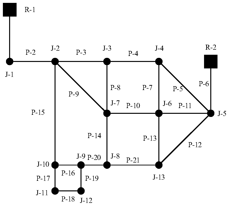
[0094] Such as image 3 As shown, the water supply network 1 is composed of 2 reservoirs, 13 nodes and 21 pipelines, and the average daily water demand is about 874 liters / second.

[0095] Although there is no specific standard on the amount of leakage, it should be ensured that the abnormal pressure value caused by the leakage is significantly different from the normal pressure value. In addition, it should be noted that the maximum leakage cannot be set too large, otherwise the water supply network will not work in the EPANET software. In this case, the node leakage is set to 3% of the total average water demand, ranging from 19L / s to 37L / s, and added to each node in turn at an interval of 2L / s to form 13 data sets, each data set 10 leak situations. Then the water supply network 1 is divided into three regions according to the FCM algorithm. The ultimate goal of the sensor layout optimization problem is to select the most representative nodes from each region to deploy pr...

Embodiment 2

[0108] Such as Figure 6 As shown, the water supply network 2 has a water tank, 23 nodes and 34 pipes. The total average water demand per day is about 282L / s, and the node leakage is set to 2% of the total average water demand, ranging from 3L / s to 8L / s, with an interval of 1L / s and added to each node in turn, similar to Example 1 Similarly, the FCM algorithm is used to cluster the areas belonging to the same area, and then semi-JMI is used to select monitoring nodes from each area. The results of the two semi-supervised methods are summarized in Table 4.

[0109] Table 4 Optimization results of two semi-supervised strategies in water supply network 2 sensor layout

[0110]

[0111] As shown in Table 4, different datasets lead to different node combinations and computation times. Finally, the selected node combination for method 1 is {1, 2, 5, 6} and for method 2 is {1, 4, 5, 18}. The average calculation time of method 1 is 2.141s. Method 2 is 1.539 times longer than M...


PUM


Abstract

The invention discloses a leakage monitoring sensor layout optimization method under an urban water supply network semi-supervised condition. The leakage monitoring sensor layout optimization method comprises the steps: step 1, pressure changes of nodes in an urban water supply network are simulated and calculated; step 2, carrying out regional division on the urban water supply pipe network through fuzzy C-means clustering according to the pressure change; and step 3, selecting representative nodes in the area through semi-supervised joint mutual information, and placing the monitoring sensoron the representative nodes.

Description

technical field [0001] The invention relates to the field of water supply pipe network maintenance, in particular to a method for optimizing the layout of leakage monitoring sensors under semi-supervised urban water supply pipe network conditions. Background technique [0002] A water supply network (WSN) is a civil infrastructure system that ensures the transportation, distribution, and supply of drinking water. With the aging of pipelines and lack of maintenance, the problem of leak detection in water supply network is becoming more and more obvious. The proportion of water leakage in the pipeline can reach 30% of the total water supply. In addition, water leakage can have serious economic and social impacts. Therefore, leak management requires novel and efficient approaches to address these challenges. [0003] Existing sensor layout optimization techniques usually presuppose the integrity of leak data location information, that is, leak localization under supervised c...

Claims


Application Information

Patent Timeline
Patent Type & Authority Applications(China)
IPC IPC(8): G06F17/50G06K9/62
Inventor 李娟王聪钱志鸿卢长刚康文炜乔乔叶心吕伟力
Owner JILIN UNIV
Why Eureka
Try Eureka