Hybrid cell type integrated IGBT device

A cell and device technology, applied in the field of hybrid cell type integrated IGBT devices, can solve the problems of reducing device switching speed and switching energy loss, etc.

Inactive Publication Date: 2019-05-24
上海擎茂微电子科技有限公司
View PDF6 Cites 4 Cited by
  • Summary
  • Abstract
  • Description
  • Claims
  • Application Information

AI Technical Summary

Problems solved by technology

The high Crss of the IGBT device reduces the switching speed of the device and also makes the switching energy loss higher

Method used


Image

  • Hybrid cell type integrated IGBT device
  • Hybrid cell type integrated IGBT device
  • Hybrid cell type integrated IGBT device

Examples


Embodiment Construction

[0018] The specific implementation manners of the present invention will be further described in detail below in conjunction with the accompanying drawings and embodiments. The following examples are used to illustrate the present invention, but are not intended to limit the scope of the present invention.

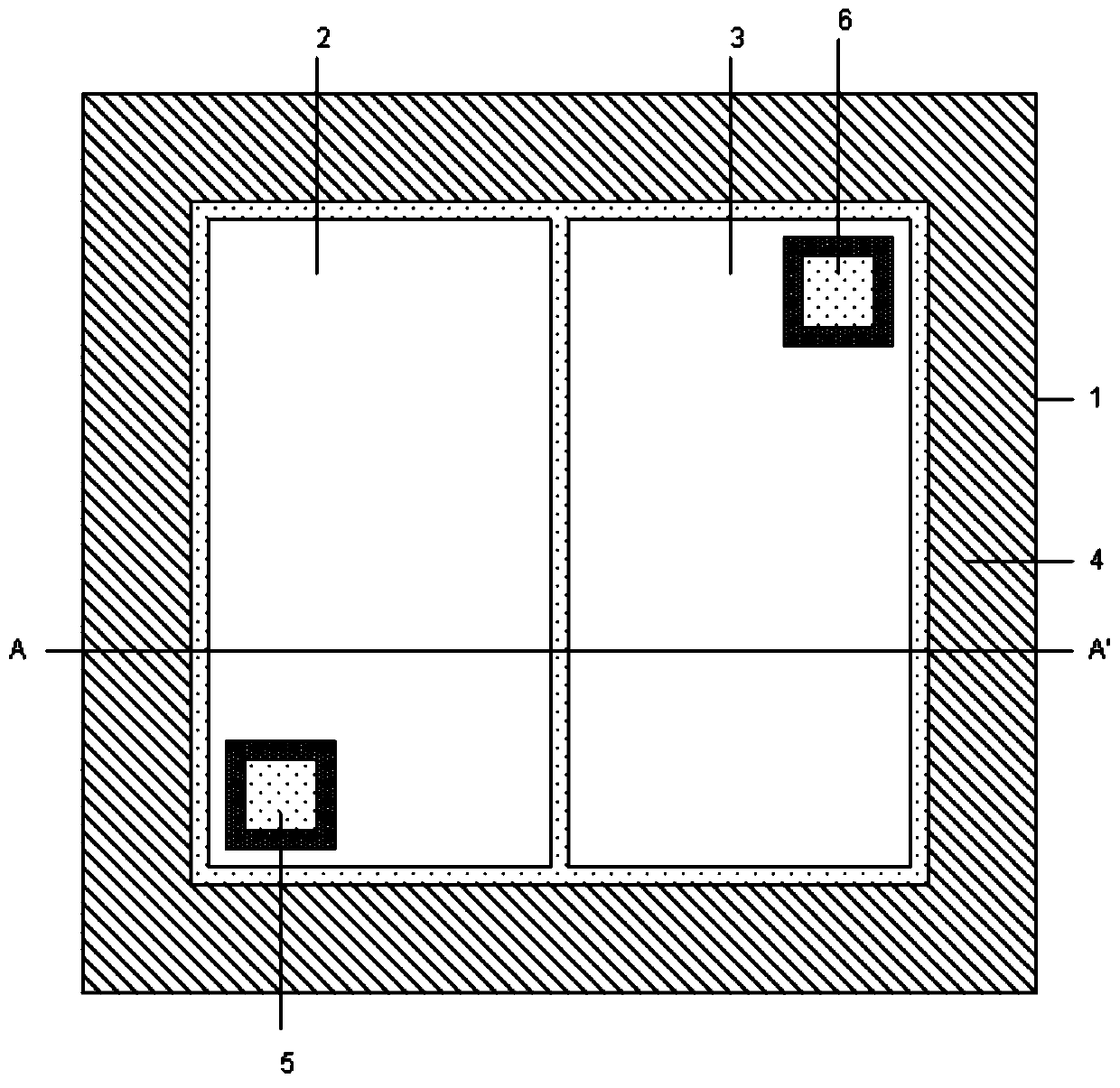
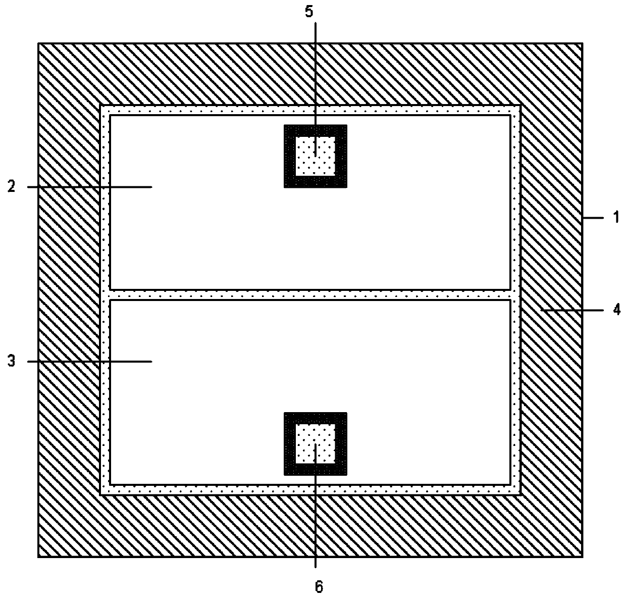
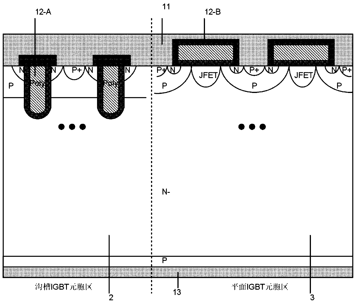
[0019] see Figure 1 to Figure 7 , a mixed cell-type integrated IGBT device according to a preferred embodiment of the present invention, the active region includes a groove cell region 2 and a planar cell region 3, and the groove cell region is composed of groove-type IGBT cells, The planar cell region is composed of planar IGBT cells.

[0020] The hybrid cellular integrated IGBT device of the present invention integrates two IGBT structures with different application characteristics into a single IGBT chip, and combines the advantages of the two IGBTs, so that the conduction voltage of the existing trench IGBT is reduced, and the current The advantages of high density,...


PUM


Abstract

The invention relates to a hybrid cell type integrated IGBT (Insulated Gate Bipolar Transistor) device. The device comprises an active region. The active region of the hybrid cell type integrated IGBTdevice comprises a groove cell region (2) and a plane cell region (3). The groove cell region is composed of groove type IGBT cells, and the plane cell region is composed of plane type IGBT cells. According to the hybrid cell type integrated IGBT device, a groove type IGBT cell structure and a plane type IGBT cell structure are arranged in a single chip at the same time. The hybrid cell type integrated IGBT device is provided with two independent control gates. The advantages of the two control gates are combined, and a better device performance is achieved.

Description

technical field [0001] The invention relates to an IGBT device, in particular to a mixed cell type integrated IGBT device. Background technique [0002] The traditional planar gate IGBT consists of gate oxide layer, planar polysilicon gate electrode, JFET region, emitter electrode, insulating dielectric layer, N+ emitter region, P well region, P+ deep well region, N-drift region, P-type collector region and Collector composition. The conductance modulation near the upper part of the traditional planar IGBT device structure is poor, and its own characteristics determine that its front-side carrier concentration is small. Current flowing through the upper part of the P-well region will generate JFET impedance, so it has a higher on-state voltage and on-state loss. Due to the large cell area in the active region of the traditional planar IGBT device, the effective channel width is small when the device is turned on, and the current density is also small. In order to increase...

Claims


Application Information

Patent Timeline
Patent Type & Authority Applications(China)
IPC IPC(8): H01L27/082H01L29/739H01L21/331
Inventor 阳平
Owner 上海擎茂微电子科技有限公司
Why Eureka
Try Eureka