Unmanned forklift based on laser slam

An unmanned forklift and laser technology, applied in two-dimensional position/channel control, navigation through speed/acceleration measurement, navigation calculation tools, etc., can solve cumulative map errors, inaccurate navigation, inaccurate cloud point information, etc. problem, achieve the effect of small navigation error and prevent the error of walking system

Active Publication Date: 2021-01-26
GUANGZHOU LANHAI ROBOT SYST CO LTD
View PDF7 Cites 0 Cited by
  • Summary
  • Abstract
  • Description
  • Claims
  • Application Information

AI Technical Summary

Problems solved by technology

Laser SLAM uses a series of scattered points (commonly called point clouds) with accurate angle and distance information presented by the laser radar to collect object information. By matching and comparing two point clouds at different times, the laser radar is calculated. Relative motion distance and attitude change, complete indoor positioning, because laser SLAM collects cloud points, no need to collect three-dimensional depth information like VSLAM, so its calculation performance is much lower than that of VSLAM, and the algorithm is simple, so it has been widely used and wireless In the field of man-machine control, however, because laser SLAM positioning needs to first use laser sensors to obtain information such as the position and angle of the target from the starting point, and then the laser SLAM algorithm builds a map for positioning, but because the laser sensor is easily affected by reflections such as dust and raindrops , so that the laser sensor obtains some inaccurate cloud point information, which will lead to cumulative errors in the subsequent map obtained by the laser SLAM algorithm, which will eventually lead to inaccuracy; Deviations like this will also lead to the problem that the deviation will accumulate and lead to inaccurate navigation;
[0004] Existing technologies such as Chinese patent application number CN201810534991.X, application publication date: 2018.12.11, which discloses a laser-based navigation AGV inertial navigation angle origin transformation and error compensation algorithm, the steps are as follows: when there is laser slam detection data The heading angle is A, the heading angle of the inertial navigation device is B, then the zero angle deviation C is A-B; through the integral of the laser slam heading angle variable a and the inertial navigation heading angle variable b, record the cumulative rotation angle of the heading angle; obtain the inertial navigation The error model of the heading angle, which compensates the inertial heading angle during the inertial navigation of the robot; sets the deviation value angle between the target heading angle dir and the current heading angle, and calculates the inertial heading angle error compensation based on the unity of zero degrees. More accurate deviation value, the present invention unifies the zero-degree angle of the heading angle of the inertial navigation device with it, and calculates the cumulative error model of the inertial navigation heading angle in real time, thereby performing error compensation on the inertial navigation heading angle; reducing the cumulative error of the current inertial navigation device , can unify the output data of the inertial navigation device, but this document uses the heading angle detected by SLAM to correct the heading angle of the inertial navigation device of the inertial system, which does not consider the deviation of the position and angle of the laser SLAM itself. Causes the laser SLAM positioning map to form a cumulative error, resulting in inaccurate positioning

Method used


Image

  • Unmanned forklift based on laser slam
  • Unmanned forklift based on laser slam
  • Unmanned forklift based on laser slam

Examples


Embodiment Construction

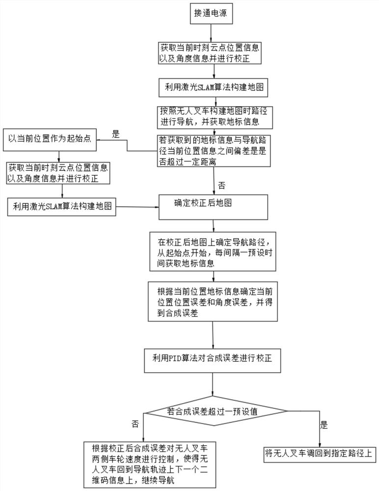
[0049] The present invention will be described in further detail below in conjunction with the accompanying drawings and specific embodiments.

[0050] Such as Figure 1 ~ Figure 3 As shown, the unmanned forklift based on laser SLAM includes the car body, with wheels on the left and right sides of the car body, and landmark information on the ground where the unmanned forklift is walking. The landmark information can be binary code information, etc. In an embodiment, the landmark information is two-dimensional code information, and the control method of the unmanned forklift includes the following steps:

[0051] S1: Turn on the power;

[0052] S2: The unmanned forklift constructs the map through the laser SLAM algorithm. The steps of constructing the map based on the laser SLAM algorithm include:

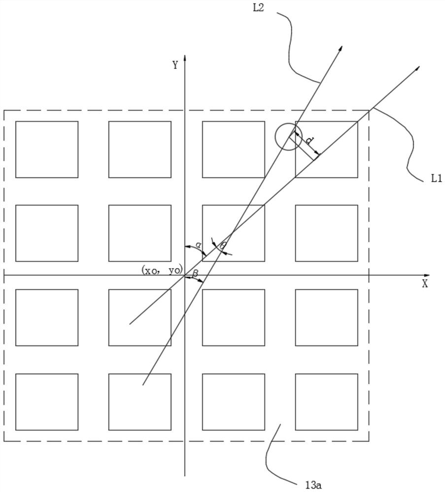
[0053] 1) Start the laser sensor to obtain the cloud point position information and cloud point angle information of the target near the unmanned forklift at the current moment, ...


PUM


Abstract

The invention provides an unmanned forklift based on a laser SLAM. A specific control method comprises the steps that a power supply is powered on; a laser sensor is started for acquiring cloud pointposition information and cloud point angle information of a target object nearby the unmanned forklift at the current moment, an extended Kalman filter algorithm is used for correcting the cloud pointposition information of the current moment to obtain a cloud point position information optimal value and a position information correction equation of the current moment, and the extended Kalman filter algorithm is used for correcting the cloud point angle information of the current moment to obtain a cloud point position information optimal value and an angle information correction equation ofthe current time; according to the obtained cloud point position information optimal value and the obtained cloud point angle information optimal value, the laser SLAM algorithm is used for obtainingestablishment of a current moment environment; current moment environment establishment of the next moment is conducted, and finally a map is formed; a navigation route of the unmanned forklift is determined, landmark information is used for correcting the current position information, map establishment is accurate, and the navigation error is small.

Description

technical field [0001] The invention relates to the technical field of unmanned forklifts, in particular to a navigation method for unmanned forklifts based on laser SLAM. Background technique [0002] SLAM (simultaneous localization and mapping, synchronous positioning and map construction) refers to the process of a moving object calculating its own position while constructing an environmental map based on the information of the sensor, and solving the positioning and map construction of robots and the like when moving in an unknown environment question. At present, SLAM is mainly used in the fields of robots, drones, and unmanned driving. Its uses include the localization of the sensor itself, as well as subsequent path planning, motion performance, and scene understanding. [0003] Due to the different types of sensors and installation methods, the implementation and difficulty of SLAM will vary to a certain extent. According to the sensor, SLAM is mainly divided into...

Claims


Application Information

Patent Timeline
Patent Type & Authority Patents(China)
IPC IPC(8): G01C21/16G01C21/20G05D1/02
Inventor 徐文斌温伟杰张伟波陈文辉区顺荣
Owner GUANGZHOU LANHAI ROBOT SYST CO LTD
Why Eureka
Try Eureka