soil drying box

An air-drying box and soil technology, which is applied in the field of soil analysis, can solve the problems of affecting the efficiency of soil testing, the inability to adjust the exhaust volume, etc., and achieve the effect of improving the efficiency of soil testing and facilitating regular replacement

Active Publication Date: 2021-03-30
江苏秋泓环境检测有限公司
View PDF12 Cites 0 Cited by
  • Summary
  • Abstract
  • Description
  • Claims
  • Application Information

AI Technical Summary

Problems solved by technology

[0004] In normal use, there is a vent hole on the door of the air-drying unit chamber, and the vent hole is only a conventional cylindrical hole. During the soil test, the amount of gas in the air-drying unit chamber needs to be discharged according to the test requirements. The test The amount of gas in the air-drying unit chamber is different for different soil types. However, the aperture of the conventional vent hole is fixed, and the aperture of the vent hole cannot be adjusted according to the actual exhaust volume, thereby affecting the test efficiency of the soil.

Method used


Image

  • soil drying box
  • soil drying box
  • soil drying box

Examples


Embodiment 1

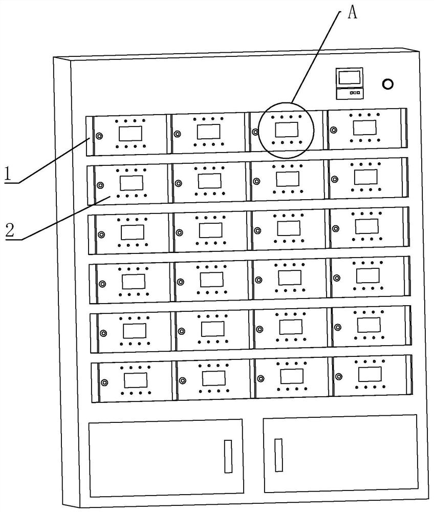
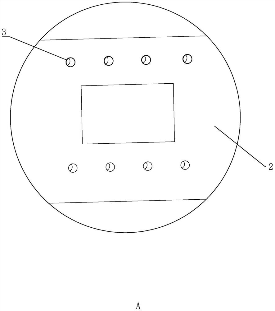
[0036] Embodiment 1: A kind of soil air-drying box, with reference to figure 1 and figure 2 , including a number of air-drying box boxes 1 evenly arranged on the air-drying box, the box body is arranged in a cuboid shape, an opening is provided on the side wall of the box body, and a box cover 2 for sealing the box body is hinged on the box body. A number of cylindrical exhaust holes 3 are provided on the box cover 2, and the exhaust holes 3 are arranged in a straight line along the horizontal direction. The upper ring of the side wall of the exhaust hole 3 is provided with an installation groove (not shown in the figure), and the installation groove is arranged in a circular shape and arranged along a direction perpendicular to the exhaust hole 3 .

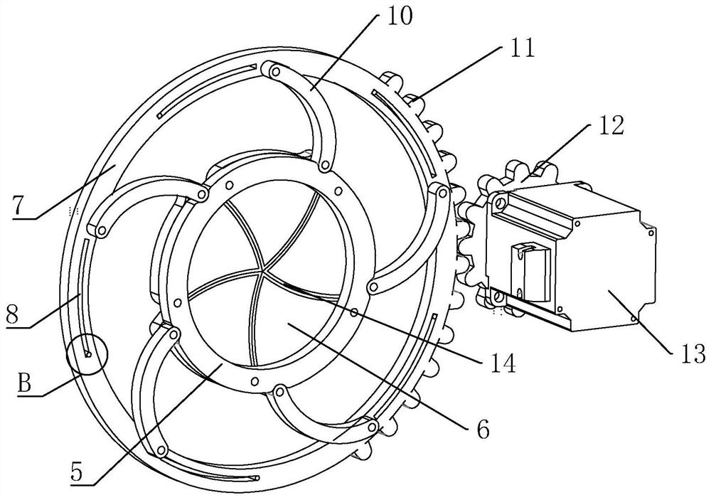
[0037] refer to image 3 and Figure 4 , a mounting plate 5 is fixedly connected to the mounting groove, the mounting plate 5 is arranged in a circular shape, and a circular plate hole is opened on the mounting plate 5, and t...

Embodiment 2

[0043] Embodiment 2: a kind of soil air-drying box, with reference to Figure 7 and Figure 8 , the difference from Embodiment 1 is that the fixing device 16 is a fixing block 163 fixedly connected to the left and right sides of the outer wall of the installation sleeve 15, and is set on the side wall of the exhaust hole 3 to cooperate with the fixing block 163 to slide the locking groove 164 , the fixing block 163 is arranged in the form of a cuboid and arranged along a direction perpendicular to the side wall of the outer tub, and the locking slot 164 is arranged along the depth direction of the exhaust hole 3 . During the sliding and plugging process of the installation sleeve 15 and the exhaust hole 3, the fixed block 163 is mated with the locking groove 164, and the mounting sleeve 15 is fixedly connected to the installation through the mating insertion of the fixing block 163 and the locking slot 164. In the groove, this fixing method is easy to operate, and is convenie...


PUM


Abstract

The invention belongs to the technical field of soil analysis, and relates to a soil air drying box. The soil air drying box comprises an air drying box body and exhaust holes arranged on the air drying box body, mounting grooves are annularly arranged at the side walls of the exhaust holes, mounting disks are fixedly connected in the mounting grooves, the mounting disks are provided with a plurality of seal plates, the sides of adjacent seal plates are rotationally laminated, the seal plates are rotationally and sealingly cover the exhaust holes, circular control panels are rotationally connected in the mounting grooves, the disk surfaces of the control panels are provided with a plurality of arc-shaped necks in the circumference, drive rods are hinged at the disk surfaces of the controlpanels, one ends, back to the control panels, of the drive rods are hinged at the end portions of the seal plates, the sides of the control panels are provided with sawteeth, control gears are rotationally connected in the mounting grooves, and the mounting grooves are internally provided with drive motors rotationally controlling the gears. The soil air drying box can regulate the hole diametersof the exhaust holes according to actual requirements and can timely regulate the gas discharge rate in the air drying unit chamber so as to improve the soil test efficiency.

Description

technical field [0001] The invention relates to the technical field of soil analysis, in particular to a soil air-drying box. Background technique [0002] Soil samples often need to be air-dried for physical and chemical analysis. After being collected from the field, spread them out in a clean indoor ventilated place until they are naturally air-dried. Exposure to the sun is strictly prohibited. Pay attention to pollution sources such as acids, alkalis, dust, and gases that may affect the test results, and air-dry them. During the process, the soil samples should be turned frequently, large soil clods should be crushed, and intrusions other than the soil such as stones should be removed. The soil samples after air drying can be analyzed for physical and chemical indicators such as soil nutrients and organic matter. When the soil sample has a high water content, natural air drying often takes a long time. [0003] At present, the Chinese patent with the publication number ...

Claims


Application Information

Patent Timeline
Patent Type & Authority Patents(China)
IPC IPC(8): G01N1/28G01N33/24F26B9/06F26B25/00
Inventor 施文莉殷国松朱丹丹卞彦殷磊
Owner 江苏秋泓环境检测有限公司
Why Eureka
Try Eureka