Magnetic resonance sounding signal noise filtering method based on variational mode decomposition

A variational modal decomposition and signal-to-noise technology, applied in geophysical measurements, instruments, etc., to expand the scope of application, improve anti-interference ability, and improve time-frequency resolution

Active Publication Date: 2019-05-31
JILIN UNIV
View PDF7 Cites 17 Cited by
  • Summary
  • Abstract
  • Description
  • Claims
  • Application Information

AI Technical Summary

Problems solved by technology

[0006] Aiming at the complexity of the noise contained in the MRS signal and the problem that the traditional EMD algorithm is prone to modal aliasing, the present invention provides a noise filtering method for magnetic resonance so

Method used


Image

  • Magnetic resonance sounding signal noise filtering method based on variational mode decomposition
  • Magnetic resonance sounding signal noise filtering method based on variational mode decomposition
  • Magnetic resonance sounding signal noise filtering method based on variational mode decomposition

Examples


Embodiment 1

[0070] This embodiment is a simulation experiment of the method of the present invention carried out under the MATLAB 7.0 programming environment.

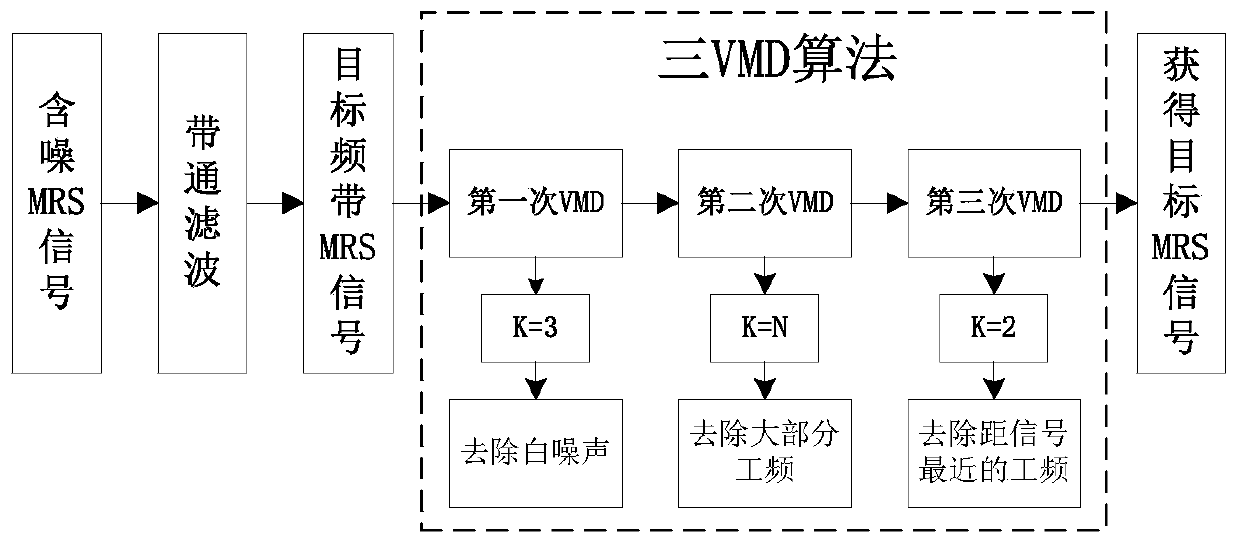
[0071] Simulation algorithm for noise filtering method of magnetic resonance sounding signal based on variational mode decomposition, refer to figure 1 , including the following steps:

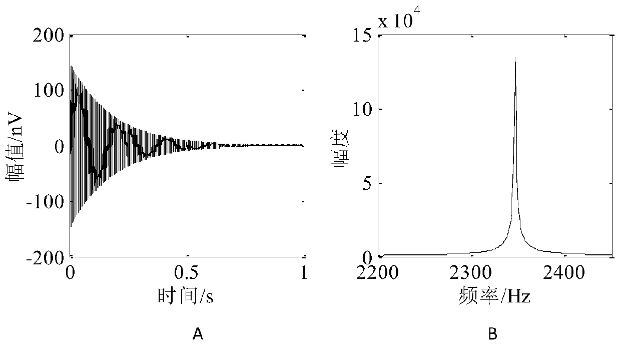
[0072] Step (1): Use the formula Construct a Larmor frequency of 2347Hz and an amplitude of e 0 150nV, the relaxation time For an ideal MRS signal of 180ms, such as image 3 shown in which, image 3 A is the time-amplitude diagram, image 3 B is the frequency-amplitude diagram. Add power frequency interference of 2250Hz, 2300Hz, 2350Hz and 2400Hz near the Larmor frequency of the signal and random noise with an intensity of -5dB to form an observed MRS signal x(t)( is a row vector), such as Figure 4 as shown, Figure 4 A is the time-amplitude diagram, Figure 4 B is the frequency-amplitude diagram;

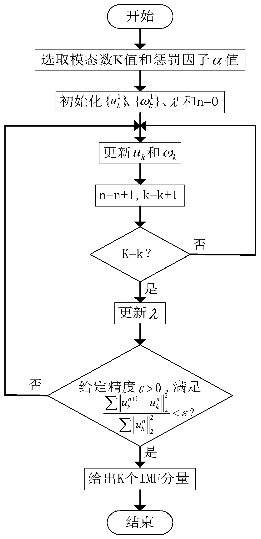
[0073] Step (2): carry out VMD alg...

Embodiment 2

[0078] In this embodiment, the MRS signal collected on the spot in Changchun Cultural Square is used as the processing object of the method of the present invention.

[0079] Noise filtering method for magnetic resonance sounding signal based on variational mode decomposition, refer to figure 1 , including the following steps:

[0080] Step 1: For a set of observed MRS signals X(t) collected by the magnetic resonance sounding (MRS) water detector, such as Figure 9 as shown, Figure 9 A is the MRS signal spectrum, Figure 9 B is the spectrum, and its signal-to-noise ratio is calculated as -8.35dB. It is preprocessed by band-pass filtering to obtain the noisy MRS signal x(t) (row vector) within the target frequency band, and its signal-to-noise ratio is calculated. SNR = 11.41dB;

[0081] Step 2: Perform Fourier transform on the observed signal x(t) after bandpass filtering to obtain its spectrum, such as Figure 10 as shown, Figure 10 A is the MRS signal spectrum, Fig...


PUM


Abstract

The invention relates to a magnetic resonance sounding (MRS) signal noise filtering field, in particular to a magnetic resonance sounding signal noise filtering method based on variational mode decomposition, which is mainly used for processing power frequency resonance noise and random white noise in the magnetic resonance sounding signals. A 'three-VMD' decomposition approach is provided to better achieve the efficient removal of noise in the noisy MRS signals. MRS signals collected by a magnetic resonance sounding water detector are subjected to band-pass filtering and Fourier transform todetermine the frequencies and the number of the power frequency resonance interference and the single frequency interference included in the MRS signals, the first, second and third VMD decompositionare employed to respectively remove the Gaussian white noise, most of the power frequency and the power frequency being the closest to the signals in the noisy MRS signals, and finally, target MRS signals are extracted and obtained. The magnetic resonance sounding signal noise filtering method can solve the customary modal aliasing problem after a traditional modal decomposition method is employed, and is high in signal-to-noise ratio and high in adaptability compared with the traditional MRS signal denoising method.

Description

technical field [0001] The invention relates to the field of magnetic resonance sounding (Magnetic Resonance Sounding, MRS) signal noise filtering, in particular to a method for filtering magnetic resonance sounding signal noise based on variational mode decomposition. Background technique [0002] Surface NMR, also known as Magnetic Resonance Sounding (MRS), is currently the only method in the world that can quantitatively determine the state of groundwater storage because it is directly sensitive to hydrogen protons in groundwater. The method excites hydrogen protons in groundwater by artificially generated alternating electromagnetic fields, and the excited hydrogen protons produce energy level transitions. When the artificial field is removed, the acquisition system receives the MRS signal induced when the hydrogen proton releases energy and moves back to realize the detection of groundwater. The general expression for a full-wave NMR signal is: This formula contains ...

Claims


Application Information

Patent Timeline
IPC IPC(8): G01V13/00
Inventor 嵇艳鞠刘健楠田宝凤庞奕荻王钰戈
Owner JILIN UNIV
Why Eureka
Try Eureka