Programmable multi-core optical fiber low-light hand

A multi-core fiber, low-light technology, applied in cladding fiber, optical waveguide light guide, nuclear engineering, etc., can solve the problem of single particle manipulation technology, and achieve the effect of good operation flexibility, reduced size, and high integration

Active Publication Date: 2020-08-07
GUILIN UNIV OF ELECTRONIC TECH
View PDF2 Cites 0 Cited by
  • Summary
  • Abstract
  • Description
  • Claims
  • Application Information

AI Technical Summary

Problems solved by technology

The particle manipulation technology possessed by these existing fiber optical tweezers is relatively simple.

Method used


Image

  • Programmable multi-core optical fiber low-light hand
  • Programmable multi-core optical fiber low-light hand
  • Programmable multi-core optical fiber low-light hand

Examples


Embodiment 1

[0025] Example 1: Stable capture of particles.

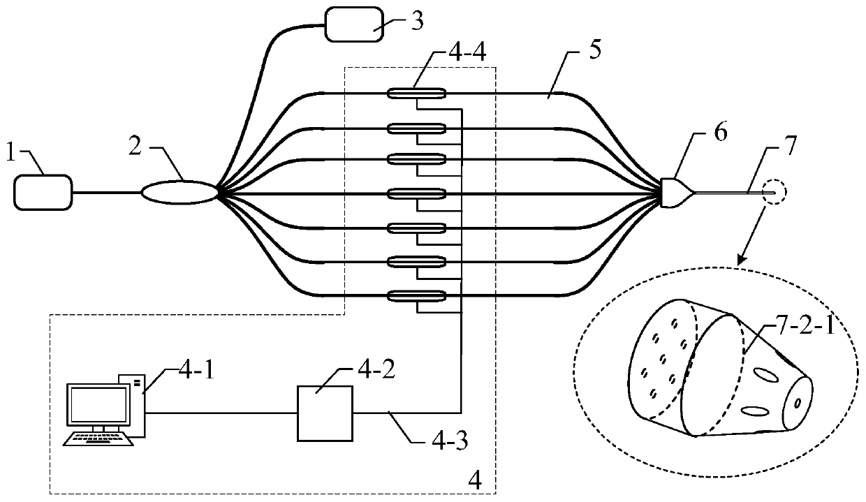
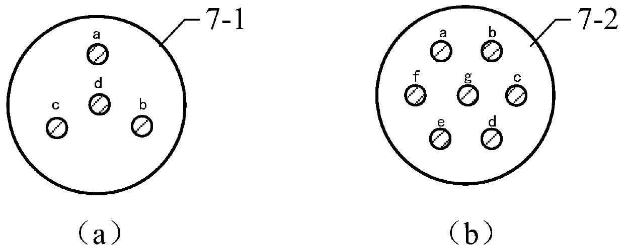
[0026] Such as Figure 4 , Figure 5 and Figure 6 As shown in (a) and (b), through the programmable module, the stable capture of particles 8 can be realized by controlling the light transmission conditions in the cores a-f of the seven-core fiber micro-light hand 7 annular distribution. Whether it is Figure 4 All the six cores a-f in (a) and (b) pass through the light, or Figure 5 The three cores a, c, and e in (a) and (b) pass through the light, or Figure 6 The four cores a, b, d, and e in (a) and (b) are light-passing. As long as the outgoing converged light field is symmetrical, stable capture of particles 8 can be achieved.

Embodiment 2

[0027] Example 2: Particle directional ejection.

[0028] Such as Figure 4 As shown, (a) (b) represents the stable capture of particles 8, (c) (d) represents the principle of particle directional ejection, and (e) represents the change of light passing through each core with time.

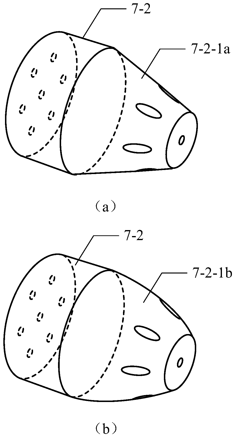
[0029] Firstly, the programmable control module 4 controls the core channels a-f to pass into the light beam 7-2-2 of equal power, and the light beam is reflected and focused by the rotationally symmetrical frustum structure 7-2-1 on the end face to form a stable trapping potential well for particle 8 for stable capture. At this time, the middle fiber core channel g is blocked from light. Next, adjust the position and direction of the optical fiber micro-light hand 7-2, and aim at the direction where the particles are to be ejected. Finally, through the programmable control module 4, the intermediate core channel g passes through a relatively high-power beam 7-2-3, as shown in Figure (c)(d), the ...

Embodiment 3

[0030] Example 3: Rotation of particles.

[0031] Such as Figure 5 , where (a) (b) represents the stable trapping of particles, (c) (d) represents the principle of particle rotation operation, and (e) represents the change of light passing through each core with time.

[0032] Firstly, the control module 4 controls the fiber core channels a, c, e to pass in light beams 7-2-2 of equal power, and the other fiber core channels are not connected to light. The light beam is reflected and focused by the rotationally symmetrical truncated cone structure 7-2-1 on the end face, forming a stable trapping potential well, and stably trapping the particle 8 . Then the control module 4 controls the core channels a, c, e to pass through the continuous stable beam 7-2-2, and the core channels b, d, f to pass through the sequence pulsed light 7-2-3 in turn, as shown in figure (e). Each beam of pulsed light can give a transverse momentum to the stably trapped particle 8, so the sequence puls...


PUM


Abstract

The invention provides a programmable multi-core fiber micro optical manipulator, characterized by comprising a laser source 1, a single-mode fiber 5, a 1*N fiber coupler 2, a power meter 3, a programmable optical path control module 4, a multi-core fiber splitter 6 and a multi-core fiber micro optical manipulator 7, wherein the programmable optical path control module 4 can control an optical signal in each branch optical path; the multi-core fiber micro optical manipulator 7 is a multifunctional microparticle operating structure made by performing microprocessing on an end frustum. The optical signal in each channel in the multi-core fiber can be controlled through programming so as to control an optical field of the multi-core fiber micro optical manipulator 7, and therefore, multifunctional operation is provided for captured particles. The programmable multi-core fiber micro optical manipulator is suitable for implementing the operations, such as capture, rotation, ejection, and vibration, for microparticles, especially various operations for micro lives and single cells.

Description

technical field [0001] The invention relates to a programmable multi-core optical fiber low light hand system, in particular to a programmable method for multifunctional manipulation of tiny particles. Background technique [0002] Optical tweezers technology refers to the technology of trapping and manipulating particles by using a single beam or multi-beam combined light field to form a trapping potential well for particles. Since Askin proposed a three-dimensional optical potential well based on a single beam of laser in the article "Observation of a single-beam gradientforce optical trap for dielectric particles" in 1986 to realize the three-dimensional space control of particles, "optical tweezers" have been This technology is gradually known by people and has been developed by leaps and bounds. The invention of optical tweezers has enabled people to obtain tools for manipulating tiny particles, which has promoted the rapid development of many interdisciplinary subject...

Claims


Application Information

Patent Timeline
Patent Type & Authority Patents(China)
IPC IPC(8): G21K1/00G02B6/02
Inventor 苑立波杨世泰
Owner GUILIN UNIV OF ELECTRONIC TECH
Why Eureka
Try Eureka