High heat flow density heat dissipation cold plate
A high heat flux density, heat dissipation cold plate technology, applied in the direction of electrical components, electrical solid devices, circuits, etc., can solve the problems of large micro-channel pressure drop, easy blockage of channels, complex processing, etc., to achieve low superheat and demand for working fluid Less heat dissipation effect
- Summary
- Abstract
- Description
- Claims
- Application Information
AI Technical Summary
Problems solved by technology
Method used
Image

Examples
Embodiment 1
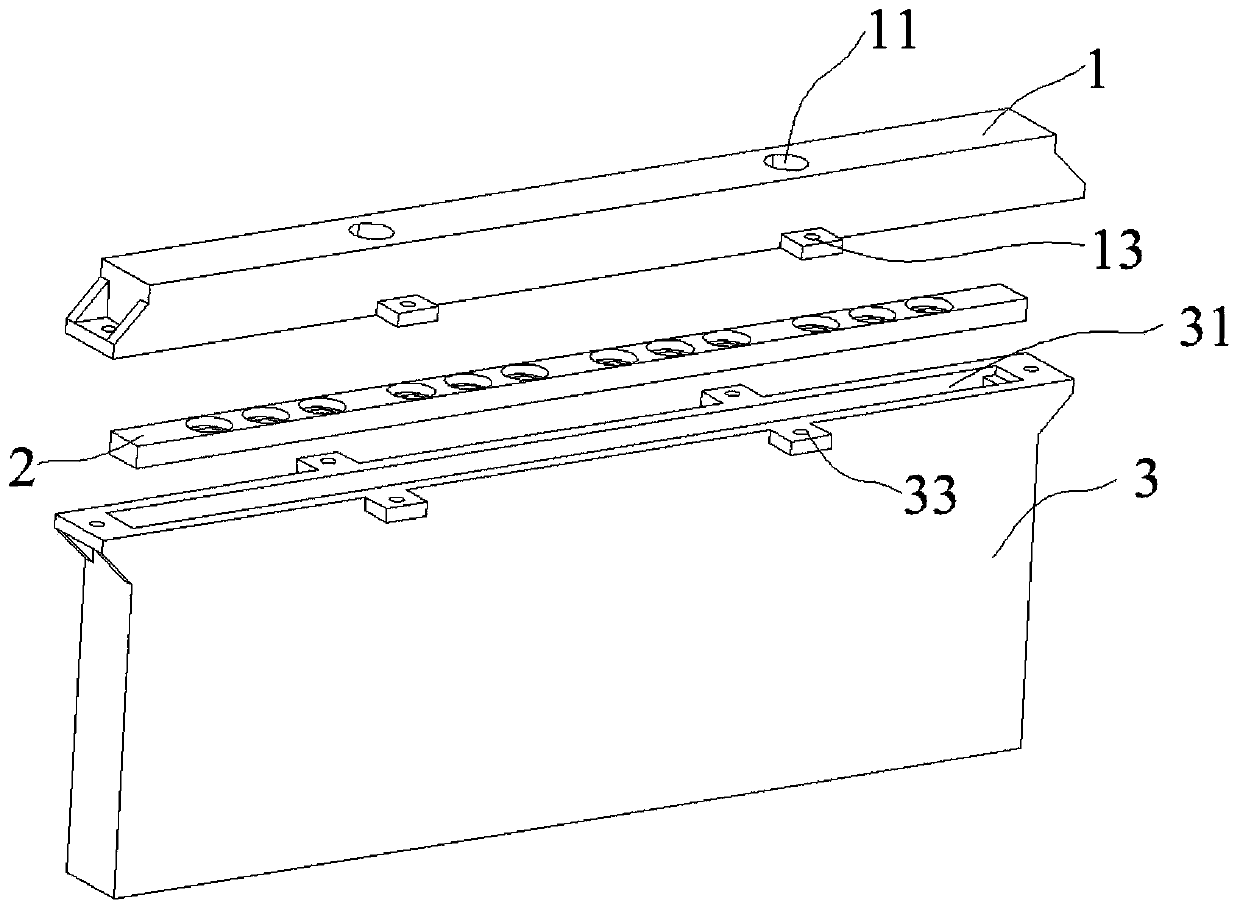
[0048] A high heat flux cooling cold plate, such as figure 1 As shown, it includes an upper cover plate 1, a micro nozzle plate 2 and a cold plate body 3; the micro nozzle 2 is located between the upper cover plate 1 and the cold plate body 3, and the upper cover plate 1 and the cold plate body 3 are passed through bolts (not shown in the figure). )connect.
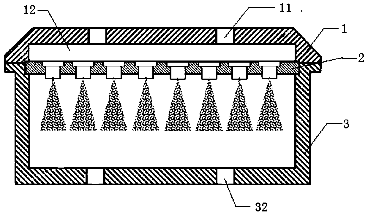
[0049] like figure 2 As shown, the upper cover 1 is columnar, and the top of the upper cover 1 is provided with a first liquid inlet 11, and the number of the first liquid inlets 11 can be set according to actual needs; Plate cavity 12, the upper end of the upper cover plate cavity 12 communicates with the first liquid inlet 11; the surroundings of the upper cover plate 1 are respectively provided with first protrusions 13, and the shape of the first protrusions 13 can be set according to actual needs. The center of a protrusion 13 is provided with a threaded hole.
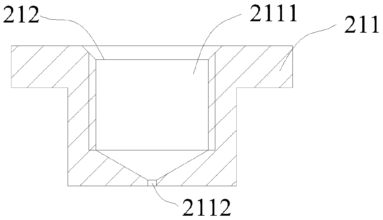
[0050] The micronozzle plate 2 is provided with som...
Embodiment 2
[0056] The difference between this embodiment and embodiment 1 is: as Figure 5 As shown, a piezoelectric atomizing nozzle is installed in the through hole of the micro-nozzle plate 2, and the piezoelectric atomizing nozzle includes a stainless steel plate 221, a piezoelectric atomizing sheet 222, a first silica gel sheet 223 and a second silica gel sheet 224, the first The silica gel sheet 223 is provided with a first through hole 2231, the second silica gel sheet 224 is provided with a second through hole 2241, the stainless steel plate 221 is provided with a third through hole 2211, and the bottom of the stainless steel plate 221 is provided with a first silica gel in turn. The sheet 223, the piezoelectric atomizing sheet 222, the second silica gel sheet 224, the first through hole 2231, the second through hole 2241 communicate with the third through hole 2211, and the piezoelectric atomizing sheet 222 is located directly below the first through hole 2231; Wherein the stain...
Embodiment 3
[0060] This embodiment also includes: Image 6 As shown, the liquid distributor 14, the liquid distributor 14 is arranged on the liquid inlet 11, the section of the liquid distributor 14 is Y-shaped, and the liquid distributor 14 is provided with 2 second liquid outlets 141 and 1 second liquid outlet 141. The liquid inlet 142 and the second liquid outlet 141 communicate with the second liquid inlet 142 respectively; the number of the first liquid inlet 11 is 2 in the present embodiment, and the inner side of the cold plate body 3 is a straight rib type, triangular Rib or pin rib.
[0061] The working principle of this embodiment: the liquid enters from the second liquid inlet 142 of the liquid separator 14 , and flows into the pressure swirl nozzle or piezoelectric atomizing nozzle from the second liquid outlet 141 .
[0062] Beneficial effects of this embodiment: through the liquid separator 14, it is convenient for the liquid to enter the pressure swirl nozzle or the piezoe...
PUM
 Abstract
Description
Claims
Application Information
 - R&D
- Intellectual Property
- Life Sciences
- Materials
- Tech Scout
- Unparalleled Data Quality
- Higher Quality Content
- 60% Fewer Hallucinations
Browse by: Latest US Patents, China's latest patents, Technical Efficacy Thesaurus, Application Domain, Technology Topic, Popular Technical Reports.
© 2025 PatSnap. All rights reserved.Legal|Privacy policy|Modern Slavery Act Transparency Statement|Sitemap|About US| Contact US: help@patsnap.com