Production method of capsule for energy accumulator

A production method and accumulator technology, which is applied in the production field of capsules for accumulators, can solve the problems of rubber performance indicators such as large discounts, elongation, tensile strength decline, and uneven seams, etc., and achieve performance indicators High, reduced process, stable material performance

Pending Publication Date: 2019-06-04
丹阳市云孚科技有限公司
View PDF5 Cites 1 Cited by
  • Summary
  • Abstract
  • Description
  • Claims
  • Application Information

AI Technical Summary

Problems solved by technology

[0002] Capsules for traditional accumulators are generally composed of two ends of the rubber cylinder connected to the front and rear heads, and the middle part of the front head is fixed and wrapped with an inner seal to install the inlet joint. During production, the rubber cylinder must first be made and vulcanized, and then the back seal is made. The cover is vulcanized and formed, and then the front seal, inner seal and inlet joint are vulcanized and molded together, and the rubber cylinder, rear seal and front seal are respectively polished, and the rear seal and front seal are respectively bonded and connected to the rubber Both ends of the barrel, and finally heat the secondary vulcanization molding in the mold. There are many procedures, the production process is complicated, and it takes a long time. The rubber barrel, the rear cover, and the front cover are vulcanized and molded separately, and then glued and polished, and the production efficiency is low. ;The rubber tube, the rear head, and the front head are bonded and connected as one. After secondary vulcanization, they are prone to become brittle, and performance indicators such as elongation and tensile strength will decrease; gluing and grinding will also make the joints uneven. The appearance is not beautiful, and the rubber performance index is greatly reduced compared with the one-time vulcanization.

Method used


Image

  • Production method of capsule for energy accumulator
  • Production method of capsule for energy accumulator
  • Production method of capsule for energy accumulator

Examples


example

[0031] Instance specification: NN6.3X486HG2331-92;

[0032] The preparation of the test piece shall be made according to the provisions of GB9865;

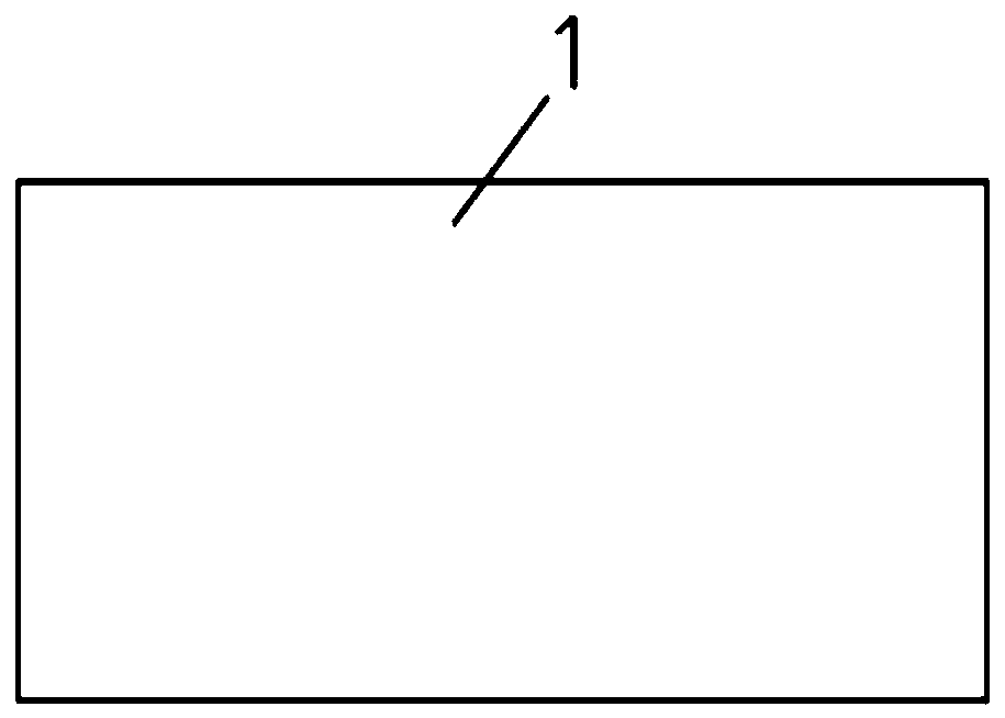
[0033] Firstly extruded by extruder figure 2 The cylindrical rubber cartridge 1 shown;

[0034] Axial length of rubber cartridge 1: 410mm, diameter 130mm, thickness 2.2±0.2mm;

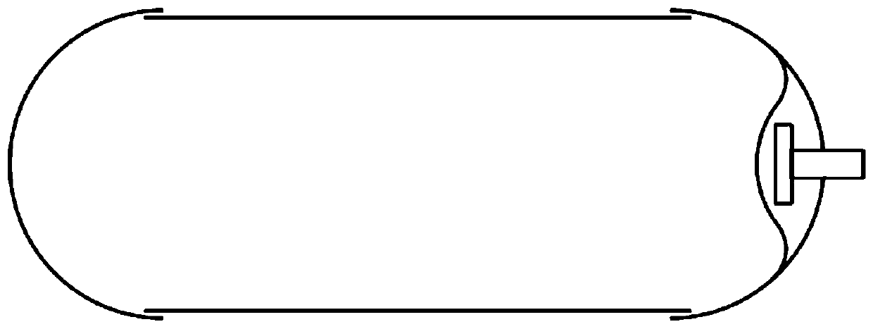
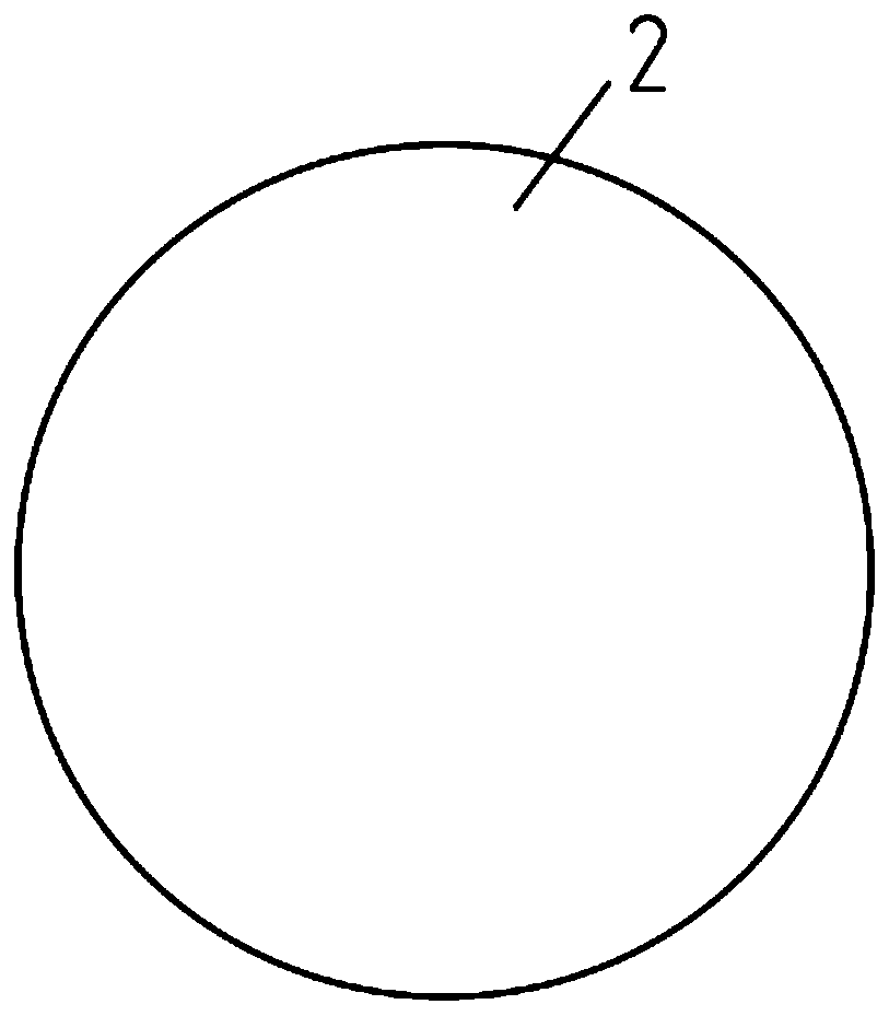
[0035] and then made by the splitting process such as Figure 3 ~ Figure 5 The shown circular back cover sheet 2, the front cover sheet 3 with a circular hole in the middle and the inner cover sheet 4 with a circular hole in the middle;

[0036] Diameter of back cover 2: 152mm, thickness: 2.2mm; diameter of front cover 3: 152mm, thickness: 2.2mm; diameter of inner cover 4: 80mm, thickness: 2.2mm;

[0037] Further, the inner seal 4 is placed parallel to the side of the front seal 3, and the inlet joint 5 of metal material is placed between the inner seal 4 and the front seal 3, and protrudes from the round hole in the middle of the front seal 3, and th...


PUM

PropertyMeasurementUnit
lengthaaaaaaaaaa
diameteraaaaaaaaaa
thicknessaaaaaaaaaa

Abstract

The invention provides a production method of a capsule for an energy accumulator. A raw rubber material is adopted to manufacture a cylindrical rubber sleeve, a rear sealing piece, a front sealing piece and an inner sealing piece through extrusion and hacking processes, wherein the middle of the front sealing piece is provided with a circular hole, and the middle of the inner sealing piece is provided with a circular hole; edges of the rear sealing piece and the front sealing piece with the inner side being connected with an inlet end socket and the inner sealing piece in a bonded mode are turned over and then fixedly connected to the exteriors of the two ends of the rubber sleeve through a bonder to constitute a capsule blank of the raw rubber material; and the capsule blank is placed into a lower mold cavity, the inlet end socket is located in a semicircular groove in a lower mold body and fixedly connected with an air feeding pipeline, after an upper mold body and the lower mold body are assembled, high-temperature steam is charged through an inlet joint, the capsule blank is expanded to be tightly attached to an inner cavity of a mold and heated by the high-temperature steam or hot air to be vulcanized, and the capsule of the overall structure is constituted. The rubber sleeve, the rear sealing piece and the front sealing piece do not need to be vulcanized respectively, polishing is also not needed after bonding, a joint is flat and smooth, the appearance is attractive, working procedures are reduced, a production process is simple, secondary vulcanization is also notneeded, material properties are stable, the quality is reliable, the consumed time is less, and thus the production efficiency is improved.

Description

technical field [0001] The invention relates to a production method of a capsule for an accumulator. Background technique [0002] Capsules for traditional accumulators are generally composed of two ends of the rubber cylinder connected to the front and rear heads, and the middle part of the front head is fixed and wrapped with an inner seal to install the inlet joint. During production, the rubber cylinder must first be made and vulcanized, and then the back seal is made. The cover is vulcanized and formed, and then the front seal, inner seal and inlet joint are vulcanized and molded together, and the rubber cylinder, rear seal and front seal are respectively polished, and the rear seal and front seal are respectively bonded and connected to the rubber Both ends of the barrel, and finally heat the secondary vulcanization molding in the mold. There are many procedures, the production process is complicated, and it takes a long time. The rubber barrel, the rear cover, and the...

Claims


Application Information

Patent Timeline
Patent Type & Authority Applications(China)
IPC IPC(8): B29C65/48B29C35/04B29L22/00
Inventor 朱文宾朱涛
Owner 丹阳市云孚科技有限公司
Why Eureka
Try Eureka