Strain sensor, forming method thereof, strain sensor array and forming method thereof
A strain sensor and strain sensing technology, applied in the field of strain sensors, can solve the problems of low integration, complex processing technology, and less research on flexible strain sensor arrays, etc., to achieve reliable connection, improve bonding reliability, and improve stability and the effect of service life
- Summary
- Abstract
- Description
- Claims
- Application Information
AI Technical Summary
Problems solved by technology
Method used
Image
Examples
Embodiment 1
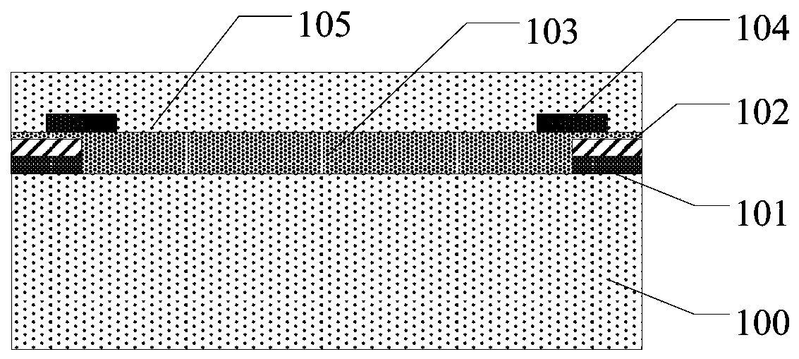
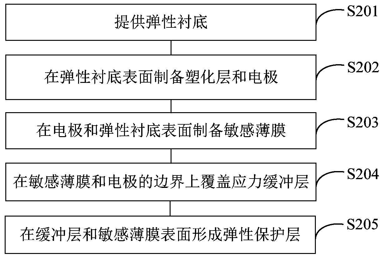
[0073] The strain sensor is completed through the following specific steps:
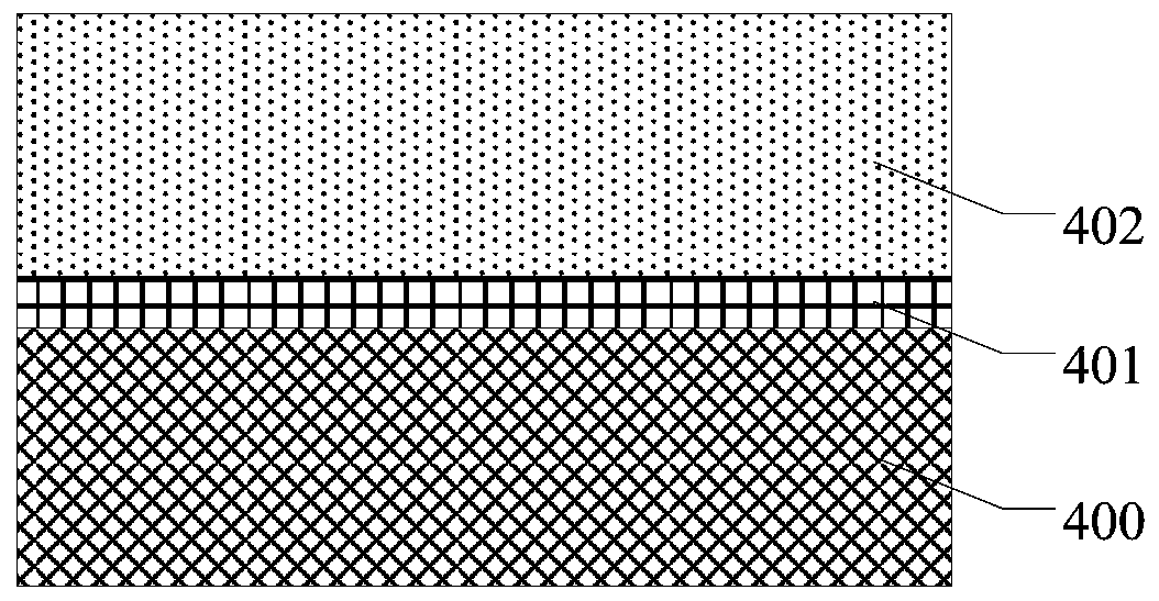
[0074] (1) Utilize ethanol solution, acetone solution and deionized water to ultrasonically clean the glass bottom plate, dry after cleaning, and use oxygen plasma or ultraviolet light / ozone to treat the substrate surface;
[0075] (2) Scrape-coat polyvinylpyrrolidone ethanol solution on the glass bottom plate, and then form a peeling layer by heating and drying;
[0076] (3) Weigh the polydimethylsiloxane material (the mass ratio of prepolymer and curing agent is 10:1), mix it evenly, scrape the mixed material on the release layer, and cure it by heating to form polydimethylsiloxane base silicone elastic substrate;
[0077] (4) The adhesive surface of the polyimide tape and the surface of the polydimethylsiloxane elastic substrate were treated with oxygen plasma, and the polyimide tape was bonded to both sides of the polydimethylsiloxane elastic substrate. side, forming a plasticized layer;
[00...
Embodiment 2
[0084] The strain sensor is completed through the following specific steps:
[0085] (1) Utilize ethanol solution, acetone solution and deionized water to ultrasonically clean the glass bottom plate, dry after cleaning, and use oxygen plasma or ultraviolet light / ozone to treat the substrate surface;
[0086] (2) Scrape-coat polyimide solution on the glass bottom plate, then form a peeling layer by heating and drying;
[0087] (3) Weigh the platinum-catalyzed silica gel material (the mass ratio of component A and component B is 1:1), mix it evenly, scrape the mixed material on the release layer, and cure it by heating to form a platinum-catalyzed silica gel elastic substrate ;
[0088] (4) The adhesive surface of the polyimide tape and the surface of the platinum catalyzed silica gel are treated with oxygen plasma, and the polyimide tape is attached to both sides of the platinum catalyzed silica gel substrate to form a plasticized layer;
[0089] (5) Prepare epoxy resin condu...
Embodiment 3
[0095] The strain sensor is completed through the following specific steps:
[0096] (1) Utilize ethanol solution, acetone solution and deionized water to ultrasonically clean the glass bottom plate, dry after cleaning, and use oxygen plasma or ultraviolet light / ozone to treat the substrate surface;
[0097] (2) Scrape-coat polytetrafluoroethylene solution on the glass bottom plate, and then form a peeling layer by heating and drying;
[0098] (3) Weigh the polydimethylsiloxane material (the mass ratio of prepolymer and curing agent is 10:1), and after mixing evenly, scrape the mixed material on the surface of the polytetrafluoroethylene peeling layer;
[0099] (4) The surface of polyethylene naphthalate film is treated with oxygen plasma, and it is attached to both sides of polydimethylsiloxane to form a plasticized layer; the film and polydimethylsiloxane are removed by vacuuming. Bubbles between the methyl siloxane, the polydimethylsiloxane elastic substrate is cured by he...
PUM
 Abstract
Description
Claims
Application Information
 - R&D
- Intellectual Property
- Life Sciences
- Materials
- Tech Scout
- Unparalleled Data Quality
- Higher Quality Content
- 60% Fewer Hallucinations
Browse by: Latest US Patents, China's latest patents, Technical Efficacy Thesaurus, Application Domain, Technology Topic, Popular Technical Reports.
© 2025 PatSnap. All rights reserved.Legal|Privacy policy|Modern Slavery Act Transparency Statement|Sitemap|About US| Contact US: help@patsnap.com


