a pulverizer

A pulverizer and chassis technology, applied in the field of pulverizers, can solve the problems of multiple grinding steps and reduced processing efficiency of bulk raw materials, and achieve the effect of increasing the pulverization effect

Active Publication Date: 2020-11-24
CHONGQING QICAIHONG CHEM
View PDF8 Cites 1 Cited by
  • Summary
  • Abstract
  • Description
  • Claims
  • Application Information

AI Technical Summary

Problems solved by technology

[0004] The object of the present invention is to provide a pulverizer to solve the problem of reduced processing efficiency caused by many steps of grinding bulk raw materials in the process of preparing powder coatings

Method used


Image

  • a pulverizer
  • a pulverizer

Examples


Embodiment Construction

[0018] The following is further described in detail through specific implementation methods:

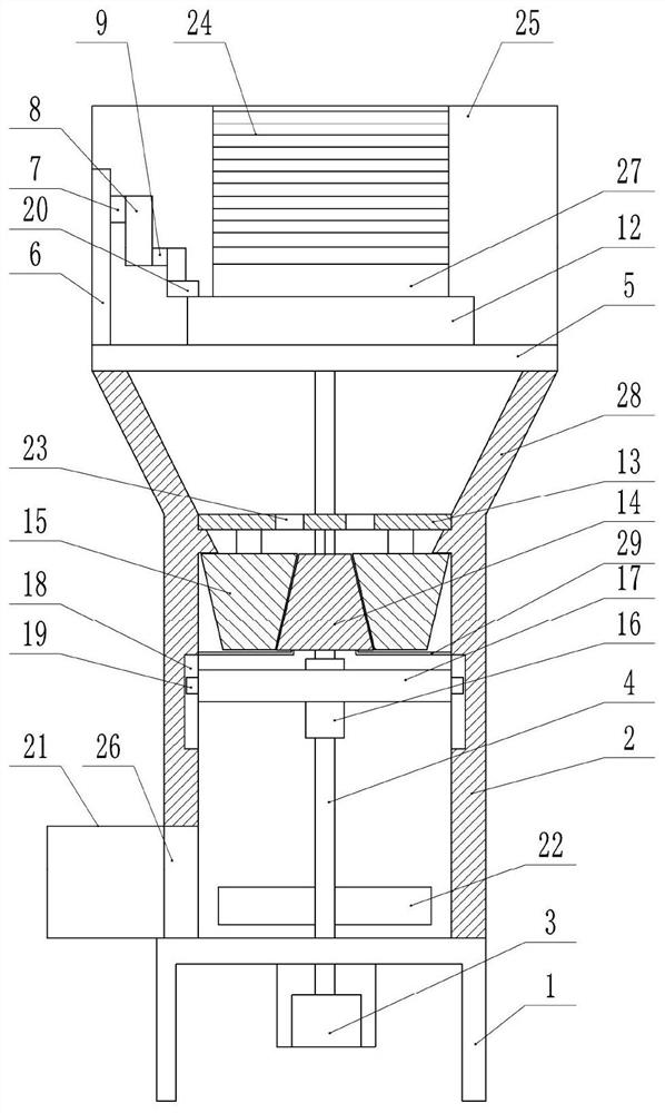
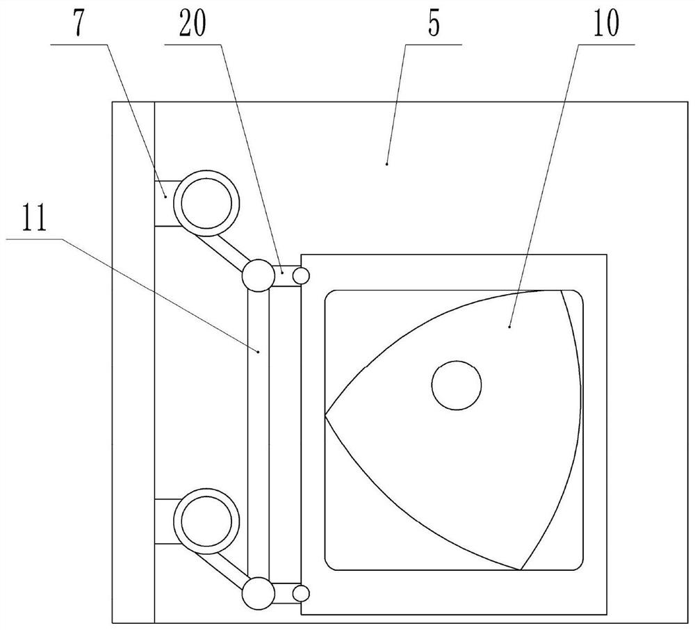
[0019] The reference signs in the drawings of the description include: frame 1, cabinet 2, motor 3, rotating shaft 4, sieve plate 5, support plate 6, cross bar 7, pole 8, swing bar 9, crushing plate 10, connecting rod 11 , square frame 12, disk 13, first grinding roller 14, second grinding roller 15, casing 16, fine sieve plate 17, vertical groove 18, slider 19, support rod 20, discharge pipe 21, pushing plate 22. Material guide hole 23, bellows 24, material inlet 25, material outlet 26, hopper 27, material guide plate 28, fixed rod 29.

[0020] The embodiment is basically as attached figure 1 As shown, a pulverizer includes a frame 1 and a driving part, the driving part is a motor 3 whose output shaft is arranged vertically upward on the frame 1, a chassis 2 is arranged on the frame 1, and the chassis 2 is installed through bearings. A vertical rotating shaft 4 is coaxially connec...


PUM


Abstract

The invention belongs to the technical field of powder grinding equipment, and particularly discloses a powder grinding machine. A rack is provided with a machine case in which a vertical rotating shaft is arranged; a driving portion drives the rotating shaft to rotate; a screen plate is arranged on the upper portion of the machine case; the portion, located above the screen plate, of the rotatingshaft is provided with a smashing portion; the position, located below the screen plate, of the machine case is rotationally provided with a disk which is fixedly arranged outside the rotating shaftin a sleeving manner; the position, located below the disk, of the rotating disk is coaxially and rotationally connected with a conical first grinding roller; a fixed rod is connected between the first grinding roller and the inner wall of the machine case; the disk is rotationally connected with a plurality of second grinding rollers in the shape of an inverted cone in the circumferential direction, and the first grinding roller and the second grinding rollers are attached and close to each other; and the portion, located above the screen plate, of the machine case is provided with a feedingport, and the lower portion of the machine case is provided with a discharging port. The powder grinding machine is mainly used for powder grinding, and solves the problem that in the process of preparing powder coating, steps for grinding blocky raw materials are more, and consequently the machining efficiency is lowered.

Description

technical field [0001] The invention belongs to the technical field of milling equipment, and specifically discloses a milling machine. Background technique [0002] Powder coating is a formula material based on new materials, with pigments and fillers. It is a new type of decorative material that has developed rapidly in recent years. It has energy-saving, pollution-free, high-efficiency, high-performance, and environmental protection. As a solvent-free coating, it has high coating efficiency, good anti-corrosion performance, one-time film formation and convenient storage and transportation, and is increasingly popular. It has three categories: thermoplastic powder coatings (PE), thermosetting powder coatings, and architectural powder coatings. [0003] Before preparing the powder coating, it is necessary to grind the bulk raw materials into powder, and then mix the powder with other raw materials in a certain proportion to prepare the powder coating. In the crushing proc...

Claims


Application Information

Patent Timeline
Patent Type & Authority Patents(China)
IPC IPC(8): B02C21/00B02C23/00B02C23/14B02C23/16B02C4/02B02C19/20B02C19/00
Inventor 宋小阳
Owner CHONGQING QICAIHONG CHEM
Why Eureka
Try Eureka