Biomass feeding device

A feeding device and biomass technology, applied in the direction of educts, granular/powdered fuel gasification, reagents, etc., can solve problems such as inability to realize pressurized operation, dangerous gas leakage safety accidents, etc., to prevent clogging and high temperature Measures, the effect of preventing hot gas from flowing back

Pending Publication Date: 2019-06-07
大连森雅能源环保设备有限公司
View PDF0 Cites 5 Cited by
  • Summary
  • Abstract
  • Description
  • Claims
  • Application Information

AI Technical Summary

Problems solved by technology

With the improvement of environmental protection requirements, a new biomass gasifier has emerged as the times require. The gasifier operates under pressure, and at the same time requires the system that supplies materials to it to be able to operate under pressure, which cannot be achieved by the above biomass feeding system. Running under pressure makes the dangerous gas in the furnace (mainly CO) leak through the biomass feeding system and cause major safety accidents

Method used


Image

  • Biomass feeding device
  • Biomass feeding device

Examples


Embodiment Construction

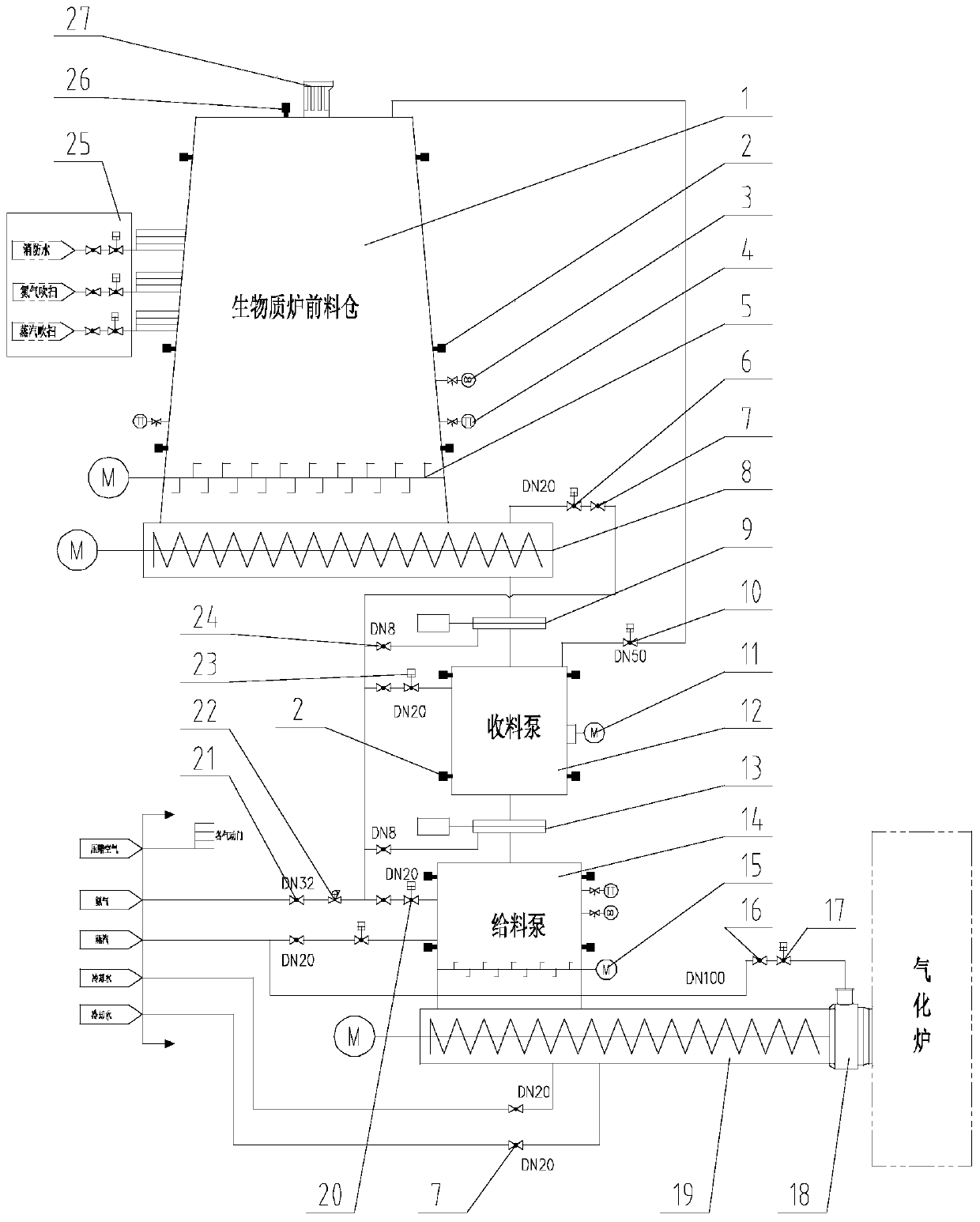
[0018] now attached figure 1 To further explain the invention, the biomass feeding device of the present invention is mainly used for feeding boilers at atmospheric pressure, and cannot satisfy the transportation of biomass materials under pressure conditions. The technical scheme adopted in the invention solves the problem of safely and stably transporting biomass materials to the boiler under the condition of positive pressure.

[0019] Such as figure 1 As shown, the biomass feeding device includes: biomass furnace feed bin 1 (1 seat), material level gauge 2 (14 sets), carbon monoxide detection device 3 (2 sets), temperature detection device 4 (3 sets), material Warehouse shifting device 5 (2 sets), double-screw pneumatic purge valve 6 (1 set), first manual maintenance valve 7 (6 sets), first double-screw feeder 8 (1 set), receiving pump Feed valve 9 (1 set), pneumatic balance valve 10 (1 set), rapping device 11 (2 sets), receiving pump 12 (1 set), receiving pump discharge...


PUM


Abstract

A biomass feed device comprises a biomass furnace front hopper, a double screw feeder, a material receiving pump, a material feeding pump, a single screw feeder and a mixer which are communicated in turn, wherein the biomass furnace front hopper is directly communicated with the shell of the double screw feeder, the bottom of the biomass furnace front hopper has no beveled edge, the material receiving pump and the material feeding pump are two square sealed containers, a material receiving pump feeding valve is arranged at that upper part of the material receiving pump, a material receiving pump discharging valve is arranged at the lower part of the material receive pump, the material entering and leaving are controlled by the material receiving pump feeding valve and the material receiving pump discharging valve, nitrogen is introduced into the material receiving pump and the material feeding pump through a nitrogen master valve, a material receiving pump intake valve and a material feeding pump intake valve, and the mixer is communicated with a gasifier. The technical scheme adopted by the invention solves the problem that the boiler safely and stably transports biomass materialsto the boiler under the positive pressure condition.

Description

technical field [0001] The invention relates to the field of biomass power generation, in particular to a biomass feeding device. Background technique [0002] Biomass power generation is the power generation using the biomass energy of biomass. It is a kind of renewable energy power generation, including direct combustion power generation of agricultural and forestry waste, gasification power generation of agricultural and forestry waste, waste incineration power generation, landfill gas power generation , Biogas power generation. Biomass power generation is a clean and renewable energy. The development of biomass power generation and the implementation of coal substitution can significantly reduce carbon dioxide and sulfur dioxide emissions and produce huge environmental benefits. my country's biomass energy resources are very rich, and the development of biomass power generation industry has broad prospects. The country vigorously promotes biomass power generation such a...

Claims


Application Information

Patent Timeline
Patent Type & Authority Applications(China)
IPC IPC(8): C10J3/50
CPCY02P20/145
Inventor 隋军王建和李立鹏张兴海隋杰
Owner 大连森雅能源环保设备有限公司
Why Eureka
Try Eureka