Digital airborne fuel oil measurement and control system
A technology of fuel measurement and control and oil quantity, which is applied in the general control system, control/regulation system, computer control, etc., and can solve the problem of insufficient peripheral interfaces of the DSP control system, complicated CPU peripheral interface circuits, and expensive measurement system chips, etc. problem, to achieve the effect of volume reduction, low cost, and cost reduction
- Summary
- Abstract
- Description
- Claims
- Application Information
AI Technical Summary
Problems solved by technology
Method used
Image

Examples
Embodiment Construction
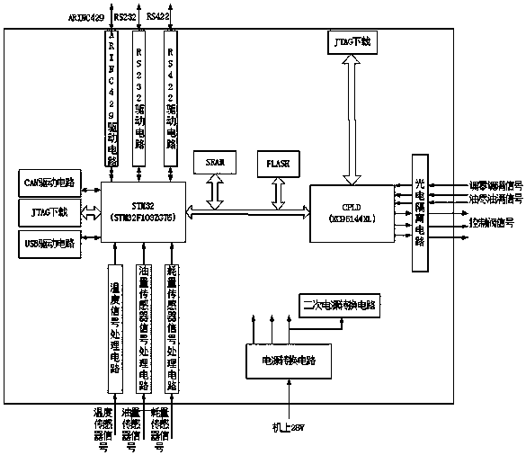
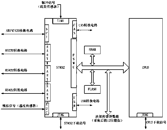
[0018] figure 1 A circuit principle block diagram of a digital on-board fuel oil measurement and control system of the present invention is shown. A digital airborne fuel oil measurement and control system of the present invention, a digital airborne fuel oil measurement and control system, includes a sensor signal processing circuit, a communication drive circuit, a photoelectric isolation circuit and a fuel quantity signal device, and is characterized in that it also includes a single-chip microcomputer STM32. The single-chip microcomputer STM32 described above is electrically connected to the sensor signal processing circuit used to process and calculate the fuel temperature, oil quantity and consumption, and the communication drive circuit used to communicate with the host computer. The described single-chip microcomputer STM32 is connected to control the digital input and output Programmable logic device CPLD, said programmable logic device CPLD connects and transmits the...
PUM
 Abstract
Description
Claims
Application Information
PatSnap Eureka turns technology decisions into work you can execute. Powered by our Innovation Knowledge Graph, it runs expert workflows across engineering, life sciences, materials and intellectual property. Get your review-ready output in minutes.


