Welding ceramic chopper

A technology of splitting knife and ceramics, which is applied in the direction of welding equipment, non-electric welding equipment, electrical components, etc., can solve the problems of shortened joint strength, joint strength, large convex area, etc., to improve wear resistance and Effects of wire bonding strength, increased wearable area, and increased wear-resistant area

Active Publication Date: 2019-06-07
苏州三环科技有限公司 +1
View PDF7 Cites 3 Cited by
  • Summary
  • Abstract
  • Description
  • Claims
  • Application Information

AI Technical Summary

Problems solved by technology

A circular unevenness is formed on the top surface of the riving knife, and there are fewer attachments on the top surface, which prolongs the life, but the height difference from the highest point of the convex part to the lowest point of the concave part is shallow, which is not wear-resistant, and When using a wire harder than gold wire such as copper wire, the life of the capillary is likely to be shortened due to a decrease in joint strength or wear
[0004] CN103658963B discloses a welding rivet, which has a body part with a top end surface for wire welding, and the top end surface has a small concave-convex shape. When viewed from the direction of the tip surface, the area of ​​the convex part is larger than the area of ​​the concave part, the inclination of the tip surface is -0.3 or less, and the average height of the tip surface is not less than 0.06 μm and not more than 0.3 μm, and there is insufficient surface roughness , the problem of easy wear
The tip portion is formed from a material in which the grain structure of the material is exposed to at least a portion of the tip portion, the surface of the portion of the tip portion having the grain structure exposed has particles having a density of at least 15 microns -2 , and the average value of the surface roughness at this portion of the tip portion having several particles is at least 0.03 micrometers, and in the case of using copper wires and other wires harder than gold wires, the reduction in joint strength or wear is likely to cause capillary reduced lifespan
[0007] It can be seen that the existing riving knife generally has problems such as easy wear, short life, insufficient surface roughness, and insufficient wire bonding strength. Therefore, it is necessary to develop a wire bonding strength that can improve wire bonding and has a long service life Lifetime Welding Ceramic Chopping Knife

Method used


Image

  • Welding ceramic chopper
  • Welding ceramic chopper
  • Welding ceramic chopper

Examples


Embodiment 1

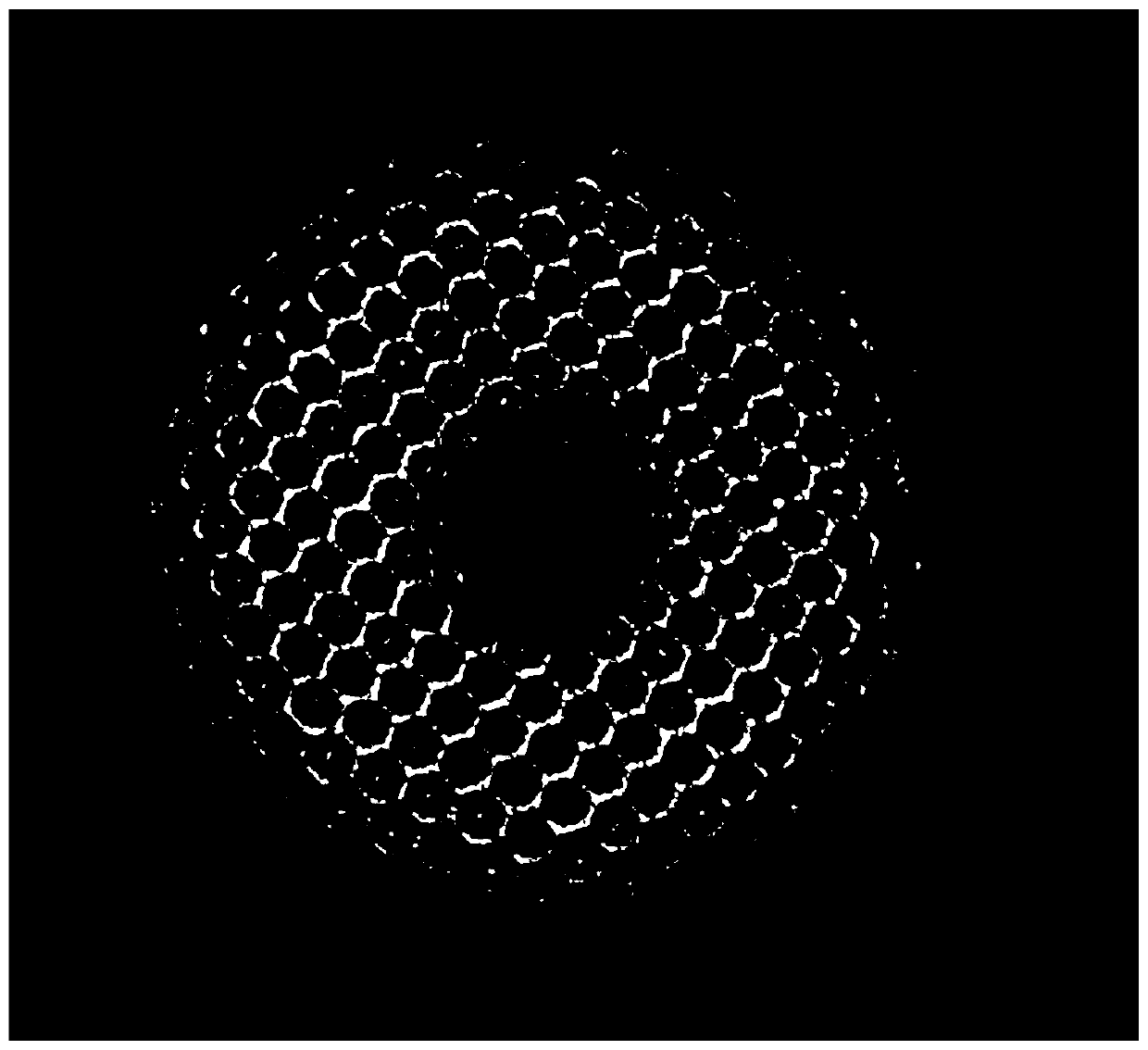
[0029] As an embodiment of the welding ceramic capillary of the present invention, the welding ceramic capillary of this embodiment includes a body, a welding tip located at one end of the body and a hole, the hole extends along the longitudinal axis of the body and the welding tip, the The tip surface of the welding tip is composed of alternately distributed convex parts and concave parts, and the convex parts are arranged in a regular hexagonal array with the welding tip as the geometric center, and the side length of the regular hexagon is 6 μm. The highest point of the convex portion and the lowest point of the concave portion form a height difference of 9 μm, the height of the convex portion is 5 μm, and the tip surface of the tip has a macroscopic surface roughness Ra of 2.0 μm. structure, the tip surface of the welding tip also has a microstructure with a surface roughness of 0.05 μm, and the convex parts and concave parts are evenly and alternately distributed.

[0030...

Embodiment 2

[0034] As an embodiment of the welding ceramic capillary of the present invention, the welding ceramic capillary of this embodiment includes a body, a welding tip located at one end of the body and a hole, the hole extends along the longitudinal axis of the body and the welding tip, the The tip surface of the welding tip is composed of alternately distributed convex parts and concave parts, and the convex parts are arranged in a regular hexagonal array with the welding tip as the geometric center, and the side length of the regular hexagon is 6 μm. The highest point of the convex portion and the lowest point of the concave portion form a height difference of 15 μm, the height of the convex portion is 7 μm, and the tip surface of the tip has a macroscopic surface roughness Ra of 3.0 μm. structure, the tip surface of the welding tip also has a microstructure with a surface roughness of 0.1 μm, and the convex parts and concave parts are evenly and alternately distributed.

[0035...

Embodiment 3

[0037] As an embodiment of the welding ceramic capillary of the present invention, the welding ceramic capillary of this embodiment includes a body, a welding tip located at one end of the body and a hole, the hole extends along the longitudinal axis of the body and the welding tip, the The tip surface of the welding tip is composed of alternately distributed convex parts and concave parts, and the convex parts are arranged in a regular hexagonal array with the welding tip as the geometric center, and the side length of the regular hexagon is 6 μm. The highest point of the convex portion and the lowest point of the concave portion form a height difference of 5 μm, the height of the convex portion is 2 μm, and the tip surface of the tip has a macroscopic surface roughness Ra of 1.2 μm. structure, the tip surface of the welding tip also has a microstructure with a surface roughness of 0.08 μm, and the convex parts and concave parts are evenly and alternately distributed.

[0038...


PUM

PropertyMeasurementUnit
lengthaaaaaaaaaa
lengthaaaaaaaaaa
surface roughnessaaaaaaaaaa

Abstract

The present invention discloses a welding ceramic chopper. The chopper comprises a body, and a welding nozzle and a hole located at one end of the body. The hole is extended along the vertical axis ofthe body and the welding nozzle, the surface of tip of the welding nozzle is formed by bulges and depressed portions which are alternately distributed, the bulges are arranged in a regular hexagon array mode by taking the welding nozzle as a geometric center, the highest point of the bulges and the lowest point of the depressed portions form height difference, and the height difference is 5-20[mu]m. The bulges and the depressed portions are designed in the surface structure of the chopper to increase the wear-resisting area, and the bulges are distributed in the regular hexagon array mode toimprove the stability of the bulges, allow the chopper not to be easily chipped and cracked in the use process and prolong the service life. The height difference between the highest point of the bulges and the lowest point of the depressed portions is large to facilitate improvement of the wearing resistance of the tip of the chopper and the bond strength of the lead, the surface of the chopper is high in smoothness, and the gold leaving degree of the tip of the chopper is effectively reduced.

Description

technical field [0001] The invention relates to the technical field of riving knives, in particular to a welding ceramic riving knife. Background technique [0002] The welding ceramic chopper is an axisymmetric ceramic tool with a vertical hole, which belongs to the precision microstructure ceramic component. Soldering ceramic rivet is a wire bonding tool used in the wire bonding process in the field of microelectronics processing, and plays an extremely important role in packaging technology. [0003] JP62-190343U discloses a rivet for improving wire bonding strength. Holes are distributed in the tip of the welding rivet, and the tip surface of the tip is composed of alternately distributed protruding parts and concave parts. The highest point of the protruding part is The height to the lowest point of the concave part is 1.5-5 μm, and the lateral distance Y between the middle points of adjacent convex parts is 3-10 μm. A circular unevenness is formed on the top surface ...

Claims


Application Information

Patent Timeline
Patent Type & Authority Applications(China)
IPC IPC(8): H01L21/60B23K20/10
CPCH01L2224/78
Inventor 郑镇宏邱基华童文欣
Owner 苏州三环科技有限公司
Why Eureka
Try Eureka