Reinforced heat dissipation flow guide device and heat dissipation module

A technology of a diversion device and a heat sink, which is applied to semiconductor devices, semiconductor/solid-state device components, electrical components, etc., can solve problems such as difficulty in ensuring heat dissipation effect and increase in power consumption.

Active Publication Date: 2019-06-07
SUZHOU LANGCHAO INTELLIGENT TECH CO LTD
View PDF5 Cites 3 Cited by
  • Summary
  • Abstract
  • Description
  • Claims
  • Application Information

AI Technical Summary

Problems solved by technology

[0004] Traditional heat sinks are plate-shaped structures arranged side by side in parallel. It is difficult to ensure effective heat dissipation under the working conditions of incr...

Method used


Image

  • Reinforced heat dissipation flow guide device and heat dissipation module
  • Reinforced heat dissipation flow guide device and heat dissipation module

Examples


Embodiment Construction

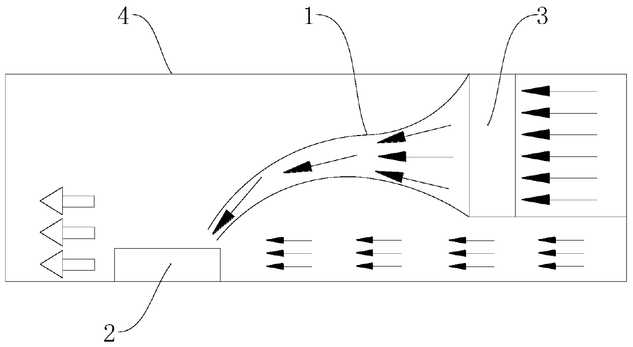
[0021] The core of the present invention is to provide an enhanced heat dissipation guide device, which utilizes Bernoulli's principle to drive a small amount of airflow to drive more air to participate in cooling, thereby increasing the cooling speed of the heat sink and improving the heat dissipation and cooling efficiency.

[0022] In order to enable those skilled in the art to better understand the technical solution of the present invention, the enhanced heat dissipation guide device of the present invention will be described in detail below in conjunction with the accompanying drawings and specific implementation methods.

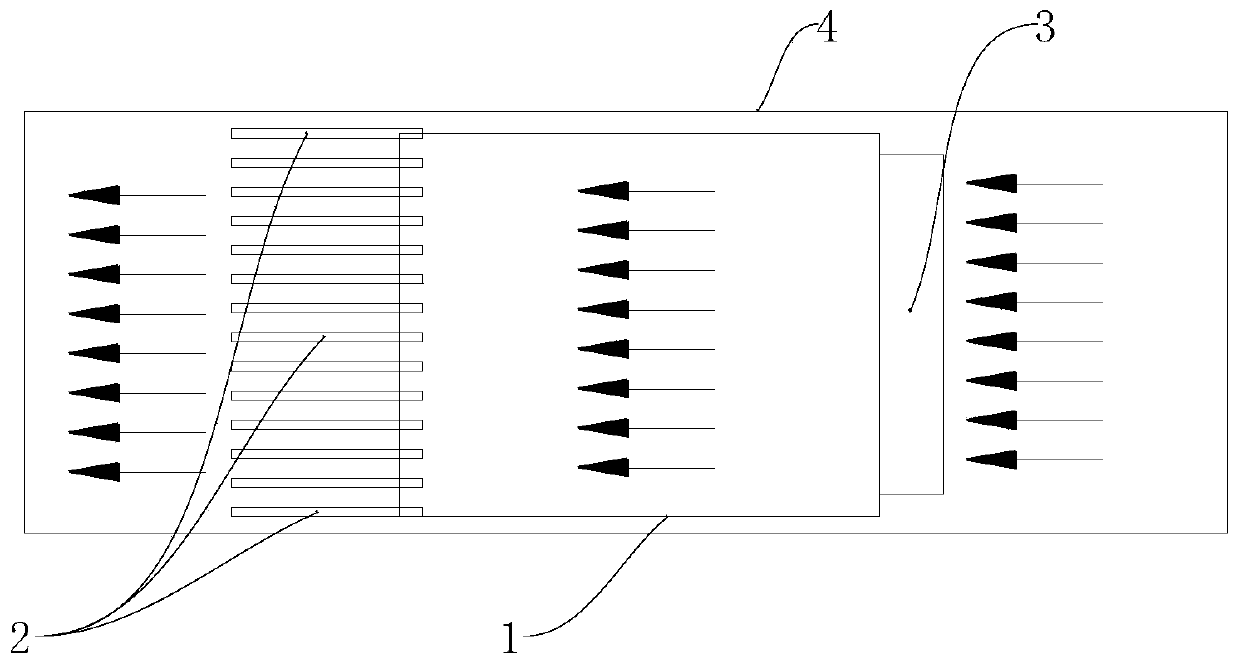
[0023] Such as figure 1 As shown, it is a front view principle diagram of the enhanced heat dissipation guide device of the present invention, figure 2 It is a schematic top view of the invented enhanced heat dissipation guide device. The enhanced heat dissipation guide device of the present invention comprises an air-inducing hood 1, the air-induci...


PUM


Abstract

The invention discloses a reinforced heat dissipation flow guide device. The device comprises an air inducing cover, and the air inducing cover is arranged between an air blowing device and cooling fins, wherein the two ends of the air inducing cover are communicated, and an air flow enters the air inducing cover from the air inlet end and flows out from the air outlet end. The air flow is guidedbetween the air blowing device and the cooling fins through the air inducing cover, and the diameter of the air inducing cover gradually decreases from the air inlet end to the air outlet end. The airinlet end is connected with the air blowing device, and the air outlet end faces the cooling fins. Under the same air volume, the air flow velocity at the air inlet end is small, and the air flow velocity at the air outlet end is large; the air blowing device blows active air to the cooling fins through the air inducing cover, the cooling fins generate low pressure after the air flow is blown outof the air inducing cover, the air pressure is lower than that of outside air, and the outside air supplements the cooling fins. The reinforced heat dissipation flow guide device provided by the invention utilizes the principle of primary efforts, more external air can be driven only by driving a small amount of active air, more air is enabled to blow through the cooling fins, the cooling speed of the cooling fins is increased, and the heat dissipation cooling efficiency is improved.

Description

technical field [0001] The invention relates to the technical field of heat dissipation equipment, and further relates to an enhanced heat dissipation guide device. In addition, the invention also relates to a heat dissipation module. Background technique [0002] There are heat-generating components in servers and other equipment, such as chips. Any electronic component is composed of many transistors. The transistors inevitably generate heat during operation. The heat must be dissipated to the surrounding environment through heat conduction, heat convection, and heat radiation. The higher the thermal conductivity of the heat dissipation material, the larger the heat dissipation area and the better the heat dissipation efficiency. [0003] With the improvement of chip performance, the heat dissipated per unit volume is getting higher and higher, and the problem of electronic heat dissipation is becoming more and more important. The heat sink is mainly composed of heat sink...

Claims


Application Information

Patent Timeline
IPC IPC(8): H01L23/467H01L23/367
Inventor 吕孟桓
Owner SUZHOU LANGCHAO INTELLIGENT TECH CO LTD
Why Eureka
Try Eureka