Dielectric filter and 5G communication equipment

A dielectric filter and dielectric resonator technology, applied in the field of filters, can solve the problems of complex manufacturing process, great technological difficulty, easy breakage, etc., and achieve the effect of reducing insertion loss, realizing simple process and large capacitance loading.

Pending Publication Date: 2019-06-07
PIVOTONE COMM TECH
View PDF1 Cites 6 Cited by
  • Summary
  • Abstract
  • Description
  • Claims
  • Application Information

AI Technical Summary

Problems solved by technology

This type of dielectric filter is easier to achieve cross-coupling with positive polarity, but it is more difficult to realize cross-coupling with negative polarity
[0004] In order to realize the negative cross-coupling of the dielectric filter, some manufacturers use multi-mode technology in the same resonator to realize the cross-coupling between degenerate modes, although the filter realized by this technology can realize positive cross-coupling and negative cross-coupling arbitrarily. Coupling, but the filter using this technology must be spliced ​​from multiple pieces of dielectric later, and the manufacturing process is complicated, which is not conducive to mass production
Some manufacturers use metallized dielectric fly rods to connect two dielectric resonators to achieve negative cross-coupling. However, it is extremely difficult to prepare surface metallized dielectric fly rods inside solid dielectric materials, and it is difficult to achieve large-scale mass production
There are also manufacturers who process a deep blind hole at the coupling window of the two dielectric resonators (see the Chinese invention patent application with the publication number CN104604022A), which is equivalent to loading a large capacitor to achieve negative cross-coupling. Technology, a dielectric filter only needs one piece of dielectric, which is conducive to mass production, but the blind hole forming negative cross-coupling is very deep, and the dielectric from the bottom of the blind hole to the opposite side is very thin. On the one hand, it requires high manufacturing accuracy and cannot be debugged, resulting in The accuracy is difficult to control, on the other hand, it will seriously affect the mechanical strength of the dielectric filter, and it is easy to break

Method used


Image

  • Dielectric filter and 5G communication equipment
  • Dielectric filter and 5G communication equipment
  • Dielectric filter and 5G communication equipment

Examples


Embodiment Construction

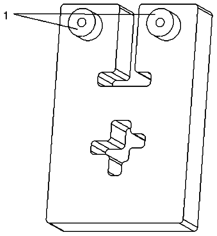
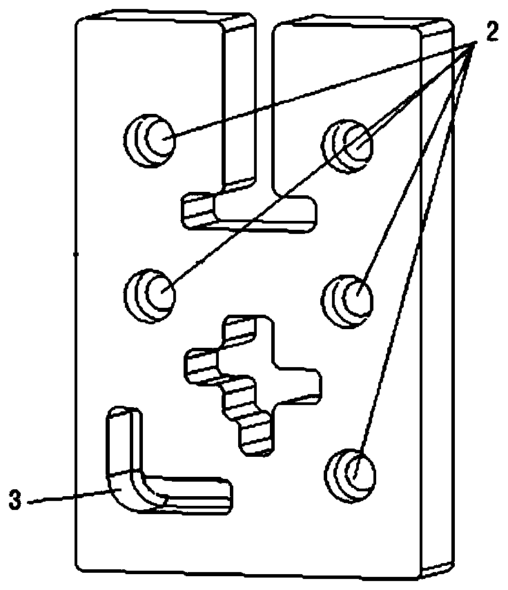
[0031] Aiming at the deficiencies of the prior art, the solution of the present invention is to realize the secondary mode resonant cavity by arranging a groove structure on the surface of the dielectric material body of the dielectric resonator, and use the secondary mode resonator technology to realize the capacitive crossover of the dielectric filter. Coupling, its realization process is simple, and the entire filter can be realized by one piece of dielectric processing, which is convenient for industrialized mass production; this scheme can realize larger capacitance loading, thereby greatly reducing the volume of the resonant cavity, while improving the Q value and reducing the insertion loss, and Does not affect the mechanical strength of the filter.

[0032] Specifically, the technical scheme of the present invention is as follows:

[0033] A dielectric filter, comprising at least three sequentially connected dielectric resonators, each dielectric resonator comprising a...


PUM


Abstract

The invention discloses a dielectric filter. The dielectric filter comprises at least three dielectric resonators in successive connection; each dielectric resonator comprises a body composed of a solid-state dielectric material and a conductive layer covered on a body surface; a groove structure covered with the conductive layer is arranged on the body surface of at least one dielectric resonators except the dielectric resonators at the head and end locations, thereby realizing the capacitive cross-coupling; the groove structure and the located dielectric resonator commonly form a secondary-mode resonant cavity. The invention further discloses a 5G communication device. Compared with the prior art, the cross-coupling with negative polarity can be conveniently realized, the mechanical strength of the filter cannot be reduced, the preparation process is simple, and the mass production is convenient.

Description

technical field [0001] The present invention relates to a filter, in particular to a dielectric filter with negative cross-coupling that can be used for 5G communication. Background technique [0002] 5G communication is the most cutting-edge communication technology at present, and various communication companies are competing to carry out related research. Among them, Sub 6GHz adopts MIMO technology, so a large number of filters need to be integrated inside the antenna, so there are higher requirements for the size and weight of the filters. Traditional metal filters are too bulky and heavy to be integrated with antennas. [0003] The miniaturized dielectric filter realized by using high dielectric constant material is an effective solution to realize the Sub 6GHz MIMO communication system because its size and weight are lower than 1 / 100 of the traditional filter. This type of dielectric filter uses a body made of solid dielectric materials (such as ceramic materials wit...

Claims


Application Information

Patent Timeline
Patent Type & Authority Applications(China)
IPC IPC(8): H01P1/20H01P7/10
CPCH01P1/20H01P1/208H01P7/10
Inventor 江顺喜殷实梁国春张丽玲冯冬琼项显王磊
Owner PIVOTONE COMM TECH
Why Eureka
Try Eureka