Chirp signal generator, chirp communication system and method for generating chirp signal

A signal generator and signal technology, applied in transmission systems, electrical components, etc., can solve problems such as inability to correctly demodulate signals, long transition time, frequency hopping, etc., to improve signal transmission rate, avoid frequency hopping, and realize The effect of high-speed communication

Active Publication Date: 2021-01-22
BEIJING SMARTCHIP MICROELECTRONICS TECH COMPANY +1
View PDF2 Cites 0 Cited by
  • Summary
  • Abstract
  • Description
  • Claims
  • Application Information

AI Technical Summary

Problems solved by technology

Figure 7 Indicates that there are 3 consecutive symbols, and the information bits sent are all 1. At this time, frequency hopping occurs between two symbols, but the phase-locked loop needs Δt time to track in place. During this period, the receiving end cannot demodulate correctly, reducing communication The demodulation performance of the system, if the proportion of this transition time is too large in the case of high symbol rate, it will lead to the failure to correctly demodulate the signal and restore the original data
[0011] Therefore, the existing chirp modulation scheme using phase-locked loop plus VCO control, due to the frequency hopping at the symbol boundary, the transition time is long, so it is impossible to achieve a high code rate chirp modulation communication system

Method used


Image

  • Chirp signal generator, chirp communication system and method for generating chirp signal
  • Chirp signal generator, chirp communication system and method for generating chirp signal
  • Chirp signal generator, chirp communication system and method for generating chirp signal

Examples


Embodiment Construction

[0036] The specific embodiments of the present invention will be described in detail below in conjunction with the accompanying drawings, but it should be understood that the protection scope of the present invention is not limited by the specific embodiments.

[0037] Unless expressly stated otherwise, throughout the specification and claims, the term "comprise" or variations thereof such as "includes" or "includes" and the like will be understood to include the stated elements or constituents, and not Other elements or other components are not excluded.

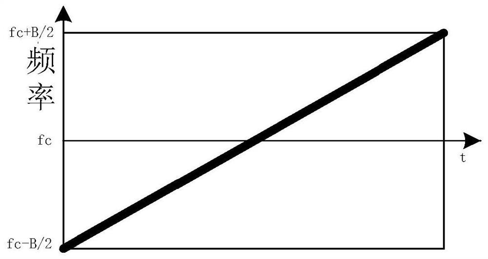
[0038] In the chirp generation method based on the phase-locked loop, in order to make the transition time of the generated Chirp signal shorter and make it suitable for high-speed communication, the present invention provides a Chirp signal generator, a Chirp communication system and a method for generating Chirp signals , the principle is to use a triangular wave instead of the existing sawtooth wave as the fundamental wa...


PUM


Abstract

The invention discloses a Chirp signal generator, a Chirp communication system and a method for generating a Chirp signal. The Chirp signal generator includes a voltage-controlled oscillator, a phase detector, a loop filter and an adder. The voltage-controlled oscillator is used to output the Chirp signal, and the oscillation frequency of the voltage-controlled oscillator can be adjusted to control the phase or frequency of the output signal. The phase detector receives the first input signal and compares the phases of the first input signal with the voltage-controlled oscillator output signal to generate the first signal. The loop filter filters out the high-frequency signal and the noise signal on the first signal to generate the second signal. The adder receives the second input signal and superimposes the second signal and the second input signal to generate a third signal, and the third signal controls the voltage-controlled oscillator to adjust the oscillation frequency. The second input signal is a triangular wave signal, including a plurality of triangular wave symbols with the same frequency waveform, and the starting and ending frequencies of the symbols are the same. The transition time for generating the Chirp signal in the present invention is shorter, and can be applied to high-speed communication.

Description

technical field [0001] The invention relates to the technical field of wireless communication, in particular to a Chirp signal generator, a Chirp communication system and a method for generating Chirp signals. Background technique [0002] Chirp signal is a spread-spectrum signal that exhibits the characteristics of linear frequency modulation, and the signal frequency changes linearly with time, also called linear frequency sweep signal. It has been widely used in radar detection, underwater acoustic communication, laser communication, ultra-wideband communication and LORA communication. [0003] In the communication system, the frequency scanning characteristics of the Chirp signal are used, such as the frequency scanning speed, the frequency scanning direction, etc. to represent the data symbols of the communication, so as to achieve the effect of frequency spreading. This communication method using the Chirp signal for frequency spreading is called Chirp spreading frequ...

Claims


Application Information

Patent Timeline
Patent Type & Authority Patents(China)
IPC IPC(8): H04B1/7085H04B1/7093
Inventor 闫发军杨季李洪强赵旭唐晓柯李思超刘佳迪
Owner BEIJING SMARTCHIP MICROELECTRONICS TECH COMPANY
Why Eureka
Try Eureka