
Connecting rod flange for fan tower barrel and fan tower barrel

A technology of wind towers and connecting rods, which is applied in the assembly of wind turbines, the configuration of installation/supporting wind turbines, and wind power generation. It can solve the problems of bottom diameter design reaching the limit, difficulty in transportation and hoisting, and increase in size and weight. Achieve the effect of being conducive to rigid mode design, convenient transportation and installation, and increasing the bottom diameter

Pending Publication Date: 2019-06-11
STATE POWER INVESTMENT CORP RES INST +1
View PDF0 Cites 3 Cited by
  • Summary
  • Abstract
  • Description
  • Claims
  • Application Information

AI Technical Summary

Problems solved by technology

Disadvantages: The diameter of the steel cylinder is limited by transportation, and the design of the bottom diameter has reached the limit
Due to the heavy weight, the prefabricated cylinder can be prefabricated in sections to reduce the weight, but also due to the increase in the single unit capacity of the wind turbine, the size and weight of the prefabricated components are also increasing, resulting in difficulties in transportation and hoisting, while the cast-in-place concrete tower is there is no such problem
In addition, there are also hybrid towers with concrete cylinders in the lower part and steel cylinders in the upper part, which can solve the problem that the bottom of the tower is too large and difficult to transport
Disadvantages: Concrete needs to be built with a mixing plant and requires prestressing treatment
Disadvantages: high on-site labor costs, a large number of bolts are used for installation, and it is difficult to align the screw holes
Disadvantages: complex design, requires a lot of bolting

Method used


Image

  • Connecting rod flange for fan tower barrel and fan tower barrel
  • Connecting rod flange for fan tower barrel and fan tower barrel
  • Connecting rod flange for fan tower barrel and fan tower barrel

Examples


Embodiment Construction

[0035] In order to make the purpose, technical solutions and advantages of the embodiments of the present invention clearer, the technical solutions in the embodiments of the present invention will be clearly and completely described below in conjunction with the drawings in the embodiments of the present invention. Obviously, the described embodiments It is a part of embodiments of the present invention, but not all embodiments. The components of the embodiments of the invention generally described and illustrated in the figures herein may be arranged and designed in a variety of different configurations.

[0036] Accordingly, the following detailed description of the embodiments of the invention provided in the accompanying drawings is not intended to limit the scope of the claimed invention, but merely represents selected embodiments of the invention. Based on the embodiments of the present invention, all other embodiments obtained by persons of ordinary skill in the art wi...


PUM


Abstract

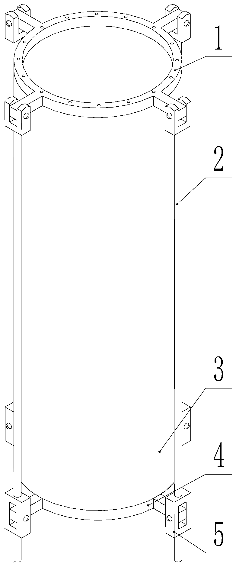
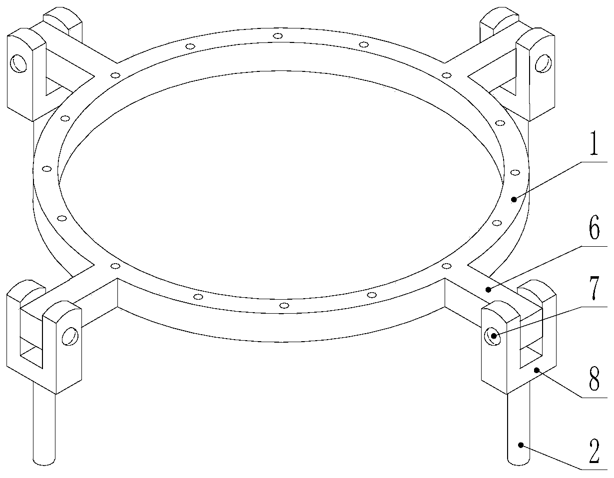
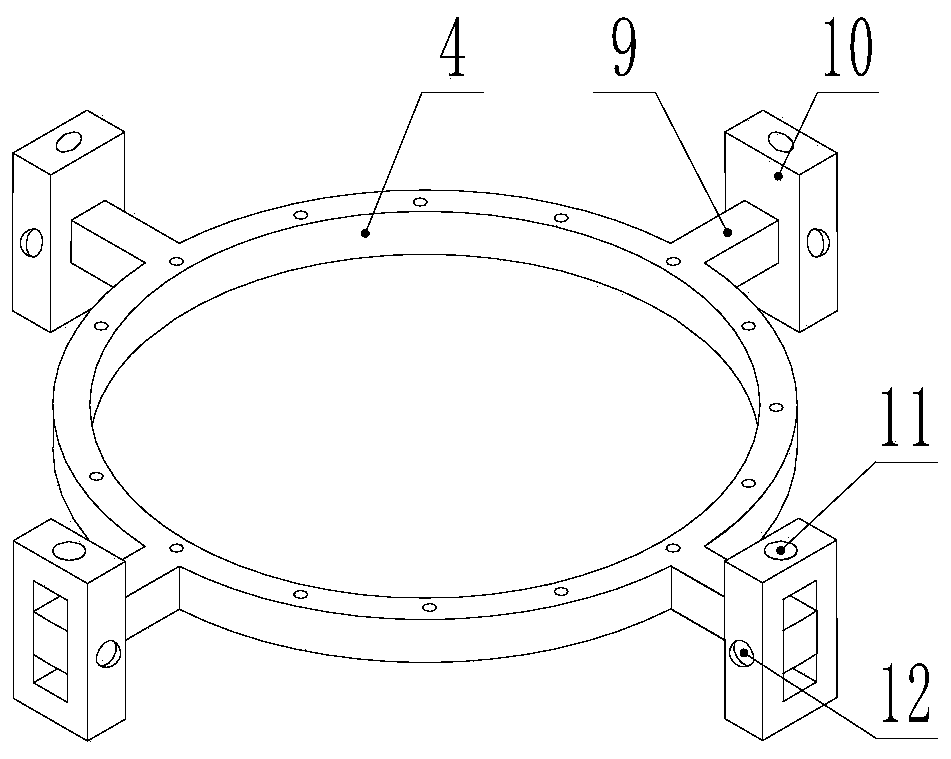
The invention relates to the field of wind power generators, in particular to a connecting rod flange for a fan tower barrel and the fan tower barrel. The connecting rod flange for the fan tower barrel comprises an upper flange ring, a lower flange ring, a connecting rod and a fixing device; and one end of the connecting rod is rotationally arranged on the upper flange ring, and the other end of the connecting rod is arranged on the lower flange ring through a fixing device. The fan tower barrel comprises a barrel body and the connecting rod flange, and the connecting rod flange is arranged onthe outer wall of the barrel body. According to the fan tower barrel, the connecting rod is arranged on the flange, and the connecting rod has a certain length and is fixed with a truss or an inhaulcable, so that the diameter of a bottom structure is effectively increased, and the static strength of the integral structure is increased; and reinforcing ribs are arranged on the barrel body, so that the static rigidity of the fan tower barrel can be improved, the deformation can be inhibited, the buckling critical load factor of the fan tower barrel can be effectively improved, the low-order integral modal frequency is improved, the rigid modal design of the tower barrel is facilitated, the energy of a vortex joint can be greatly changed, and the design of anti-vortex-induced vibration is facilitated.

Description

technical field [0001] The invention relates to the field of wind power generators, in particular to a connecting rod flange for a fan tower and a fan tower. Background technique [0002] The tower, as the supporting structure, is the main component of the wind power generation system. Under the wind load, the force and dynamic response of the tower itself have a great influence on the entire generator structure; and interact with the rotation of the wind rotor, the force of the entire structural system is very complicated, and the tower and the wind rotor Coupling occurs, so it is necessary to conduct structural analysis of the tower. [0003] The tower structure is fixed on the ground, and its mechanical model is equivalent to a cantilever beam. Under the action of lateral load, the upper section is smaller and the lower section is larger. The wind wheel is located on the top of the tower as a large structure. [0004] At present, the mainstream towers mainly include all...

Claims


Application Information

Patent Timeline
Patent Type & Authority Applications(China)
IPC IPC(8): F03D13/10F03D13/20
CPCY02E10/728Y02E10/72
Inventor 卢华兴燕鹏夏海鸿李怀林杨万强李高盛曹菡羊浩于文涛徐猛
Owner STATE POWER INVESTMENT CORP RES INST
Learn More