3D printer for metal powder

A 3D printer and metal powder technology, applied in the direction of additive processing, etc., can solve the problems of manpower consumption, difficulty in monitoring the quality of powder coating, and lower product quality, and achieve the effects of saving manpower and material resources, simple and convenient handling, and reasonable structural design

Active Publication Date: 2019-06-14
HANGZHOU HIMALAYA INFORMATION TECH
View PDF8 Cites 11 Cited by
  • Summary
  • Abstract
  • Description
  • Claims
  • Application Information

AI Technical Summary

Problems solved by technology

[0003] At present, in the SLS forming process, there are still the following problems to be solved: ① It is difficult to monitor the powder quality
The quality of powder spreading has an important influence on the quality of the formed parts. When the powder is spread unevenly, it is easy to cause internal defects of the formed parts, thereby reducing product quality and even producing waste products. In the prior art, the powder is only spread on the forming cylinder through the powder spreading roller. However, when the powder spreading roller is moving, the metal powder at one end of the powder spreading roller will tend to move to both sides of the powder spreading roller, resulting in the lack of metal powder in the middle part of the forming cylinder, and during the movement and rolling process of the powder spreading roller There may be some powder sticking to the spreading roller, causing potholes on the spreading surface
②The preheating of the formed powder takes a long time, which increases a lot of processing time. There are two main heat sources for the preheating of the powder during the powder spreading process. Powder preheating
The existing technology is to preheat the new powder through the preheating system after laying the new powder on the formed steel. Since the SLS forming is formed by superimposing layers of laser sintering, it will be preheated after each layer of new powder is laid. Thermal operation, making the molding time of the part greatly lengthened
③When the parts are processed, the parts need to be taken out from the forming cylinder. At this time, the upper part of the parts is covered with a large amount of powder. The staff needs to take out the parts and powder in the forming cylinder at the same time, and then remove the powder on the surface of the parts through the vacuum device , the operation is troublesome and consumes a lot of manpower and material resources
④In the existing equipment, when a part is processed, it is necessary to manually add powder to the printer, and when adding powder, it will cause a large amount of powder to fly, and the operator needs to wear a dust mask to operate, which not only consumes a lot of manpower, It will also affect the health of operators

Method used


Image

  • 3D printer for metal powder
  • 3D printer for metal powder
  • 3D printer for metal powder

Examples


Embodiment Construction

[0036] The present invention will be further described below in conjunction with accompanying drawing:

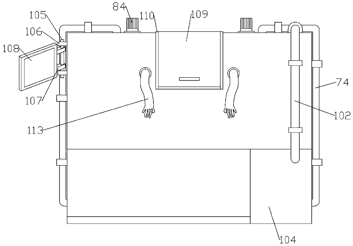
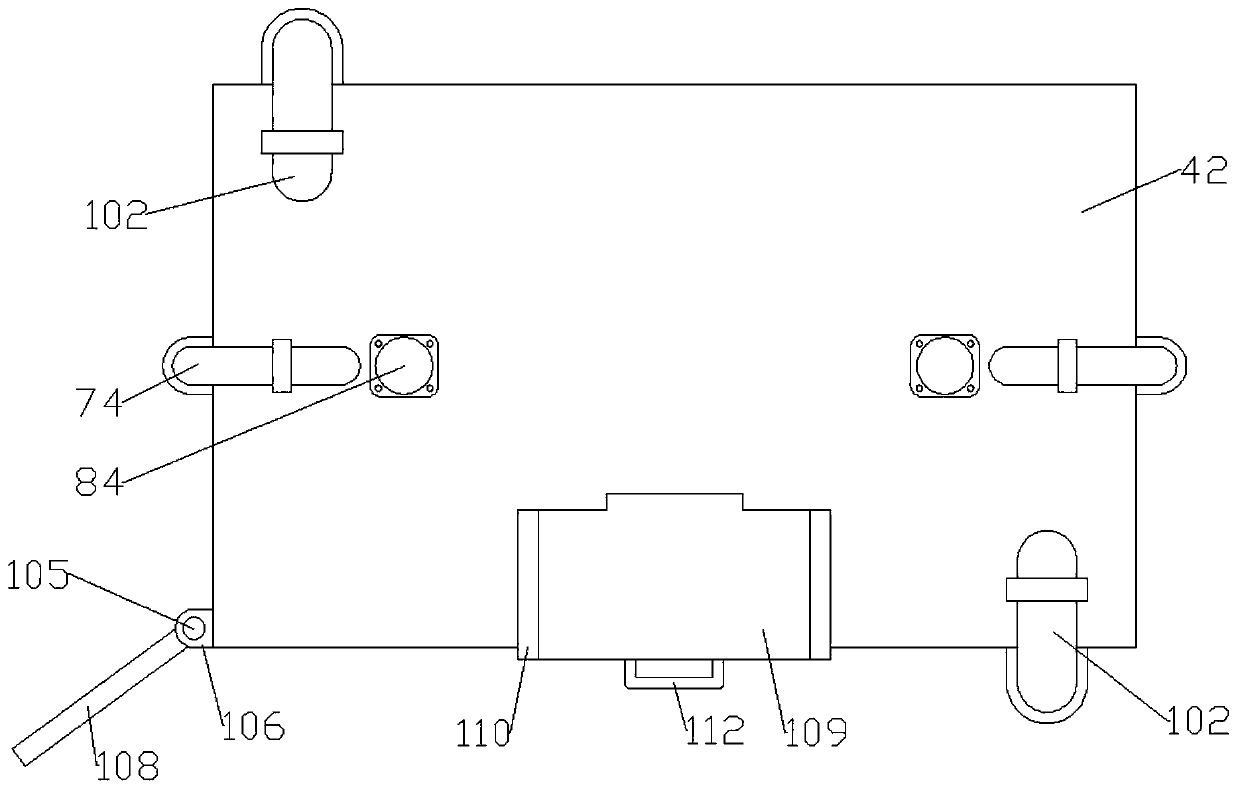
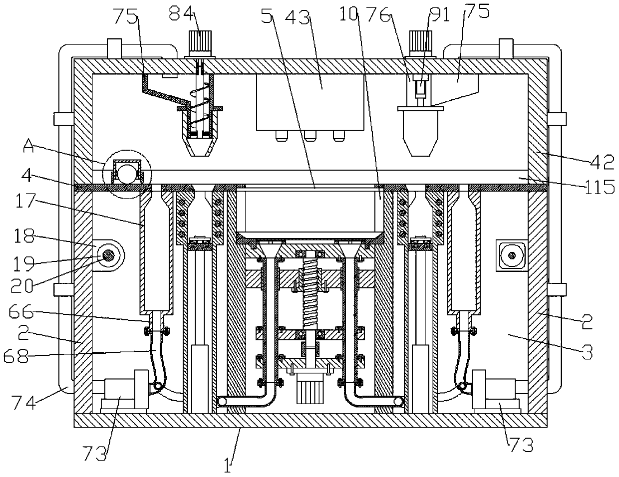
[0037] Refer to attached Figure 1-19: A metal powder 3D printer in this embodiment, comprising a base plate 1, the upper end of the base plate 1 is fixedly connected with the first support plate 2 on the left and right sides, and the upper side of the front and rear ends of the base plate 1 is fixedly connected with the second The support plate 3, the upper ends of the first support plate 2 and the second support plate 3 are fixedly connected with the operation plate 4, and the center position of the upper end of the operation plate 4 is provided with a processing groove 5, and the inner side of the upper end of the processing groove 5 is fixedly connected with the limit ring 120 , the left and right ends of the processing groove 5 are provided with powder outlet grooves 6 opened on the operation panel 4, and the left and right ends of the powder outlet groove 6 are provid...


PUM


Abstract

The invention relates to a 3D printer for metal powder and belongs to the field of 3D printing equipment. According to the 3D printer for the metal powder, the structural design is reasonable, operation is convenient, the powder laying quality is good, the powder is preheated uniformly, the part machining time is greatly shortened, formed parts are taken easily and conveniently, automatic powder adding operation can be achieved, a large quantity of manpower and material resources are saved, and an operator is prevented from inhaling a large amount of the powder. According to the adopted technical scheme, a first electric push rod is mounted on the inner side of a powder outlet sleeve, a lifting device is mounted on the inner sides of a connecting plate and a positioning plate, a conical hole, a shielding plate, a jacking rod and a guiding pipe connected with the conical hole are arranged on a lifting plate to suck the powder around the parts, an electric heating pipe is arranged on theinner side of the upper end of the powder outlet sleeve to preheat the powder, an anti-sticking part is arranged on a powder laying roller, a sealing cover is mounted on an operating panel, and a feeding sleeve, a telescopic sleeve and a feeding screw are arranged at the upper end of a sealing cover to achieve material-adding operation.

Description

technical field [0001] The invention relates to the field of 3D printing equipment, in particular to a metal powder 3D printer. Background technique [0002] Selective laser sintering (SLS) technology is a kind of 3D printing technology. SLS uses laser to selectively layer-by-layer sinter solid powder, and make the sintered solidified layers superimposed to form parts of the required shape. The whole process is as follows: when working, the powder cylinder piston (powder feeding piston) rises, and the powder spreading roller evenly spreads a layer of powder on the forming cylinder, and the computer controls the two-dimensional scanning trajectory of the laser beam according to the prototype slice model. The solid powder material is selectively sintered to form a layer of the part. After one layer is sintered, the piston of the forming cylinder is lowered by one layer thickness, and the powder spreading system spreads new powder, and the laser beam is controlled to scan and ...

Claims


Application Information

Patent Timeline
Patent Type & Authority Applications(China)
IPC IPC(8): B22F3/105B33Y30/00B33Y40/00
Inventor 祝勇仁赵庆洋范有赖全忠吴俊毛德峰
Owner HANGZHOU HIMALAYA INFORMATION TECH
Why Eureka
Try Eureka