Supercharge Your Innovation With Domain-Expert AI Agents!

Telescopic boom cable manual operation forklift

A telescopic arm, forklift technology, applied in the direction of lifting device, etc., can solve the problems of lack of brake and braking device, low efficiency, faster extraction speed, etc., and achieve the effect of saving human resources and improving efficiency

Active Publication Date: 2021-01-15
张若玮
View PDF4 Cites 0 Cited by
  • Summary
  • Abstract
  • Description
  • Claims
  • Application Information

AI Technical Summary

Problems solved by technology

At present, when laying cables in the power system, two methods are mainly used. One is to use the crane to lay out the wires. The limitations of the construction site must be considered when using the crane to lay out the wires. , and this operation method not only requires the construction personnel to expend a lot of physical strength, but also easily increases the torque of the cable itself or damages the cable insulation layer
The other is to rely on the cable pay-off rack or the cable pay-off car to pay out the wires. When in use, the cable reel is installed on the cable pay-off rack or the cable pay-off car. In existing applications, the cable reel is generally lifted by lifting equipment. Generally, two operators are required to cooperate, one operator controls the lifting equipment, and the other operator loads the rotating shaft of the cable reel into the cable pay-off The operation is complicated and the efficiency is low; then the cable pay-off frame or the cable pay-off vehicle is pulled by the traction device to the target position for pay-off, and the current cable pay-off frame needs to be placed on a flat Otherwise, the cable pay-off frame may roll over during the cable pulling process. The usually used cable pay-off vehicle is too large in size and has high requirements on the construction site. It must also be equipped with lifting equipment.
In addition, because the location of the wire is often changed, it is very laborious for the cable pay-off frame or the cable pay-off vehicle to transfer in a narrow place. When transferring or finishing work, it needs to be pulled back by a traction machine, which is limited by the site. Large, many construction sites do not have the conditions to use large pay-off vehicles
[0003] In practical applications, there are many occasions where only a small amount of cables need to be laid, or the cables are relatively thin. At this time, the cable reel is relatively light, and the weight generally does not exceed 500kg. If the load is too large, if you continue to use lifting equipment, the efficiency will be low, the operation will be inconvenient, and the scope of application will be limited by the lifting equipment
[0004] The existing pay-off device lacks a braking device. When the cable is pulled out, at the beginning, because there are many cable rolls and the mass is large, the friction force of the pay-off reel when the cable is pulled is relatively large, so the speed of cable extraction Slower, when the cable on the pay-off reel is drawn less and less, the cable roll becomes less, the mass also decreases, the friction force decreases, and the extraction speed becomes faster. At the same time, under the action of inertia, the cable is released after the extraction stops. The disc will continue to rotate, causing the cable to be thrown out and fall to the ground. During the process of pulling and laying the cable, the surface of the cable will rub against the rough ground, causing the insulating layer to be worn, shortening the service life of the cable, and in severe cases, the insulating layer will be worn out and The wire core is exposed, and there is a big safety hazard after power-on
[0005] In the existing technology, the quality and efficiency of cable handling and laying have not been effectively solved. From the warehouse to the construction site, the cable reel needs to be hoisted by a crane and placed on the transport vehicle, and then workers need to put the cable The wire reel is fixed on the carriage, and after being transported to the construction site, the cable is paid out by a crane or hoisted to the auxiliary device for laying out the cables. The process is cumbersome, labor-intensive, and construction efficiency is low.
In addition, there are too many links in the whole process, and it is very easy to increase the torque of the cable itself or damage the cable insulation layer, which will bring hidden dangers to the safety of power supply in the future.

Method used


Image

  • Telescopic boom cable manual operation forklift
  • Telescopic boom cable manual operation forklift
  • Telescopic boom cable manual operation forklift

Examples


Embodiment Construction

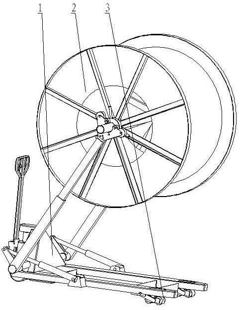
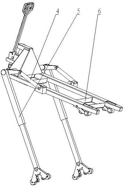
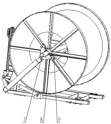
[0026] As shown in the figure, the two ends of the manual forklift 1 are equipped with a left (right) telescopic arm assembly 5, and a telescopic arm assembly lifting device 4 is provided between the left (right) telescopic arm assembly 5 and the manual forklift 1. Drive the left (right) telescopic arm assembly 5 to perform upward, horizontal and downward rotation actions.

[0027] A telescopic device is set between the rear arm and the forearm in the left (right) telescopic arm assembly 5, so that the forearm moves along the set track, and the forearm moves telescopically under the drive of the power device; roller 9 and pulley block 8 are arranged at the end of the forearm , the setting of roller 9 is convenient for the voluntary boarding or getting off of this forklift;

[0028] The lower part of the manual forklift 1 is provided with a shelving device 6. When the manual forklift 1 is lowered and the front and rear moving wheels 3 are all retracted, the shelving device 6 is...


PUM


Abstract

The invention provides a telescopic arm cable manual working forklift which integrates cable reel loading and unloading, work scene transportation or transferring and cable unwinding functions together, and the telescopic arm cable manual working forklift is very smart, has the ability to get on or off by itself, facilitates transportation along with a vehicle together with a cable reel, enables the labor intensity and work efficiency of electric workers to be improved simultaneously, and greatly improves the safety. The telescopic arm cable manual working forklift is characterized in that left (right)-direction telescopic arm assemblies are arranged at the two ends of the manual forklift, a telescopic arm assembly lifting device is arranged between the left (right)-direction telescopic arm assemblies and the manual forklift, and the left (right)-direction telescopic arm assemblies are driven to do upward, horizontal and downward rotation; a telescopic device is arranged between a reararm and a front arm of each left (right)-direction telescopic arm assembly, and each front arm is driven by a power device to do telescopic movement; and the end of each front arm is provided with aroller and a pulley block, and a shaft rod penetrates through a shaft hole in the cable reel to be arranged in the pulley block.

Description

technical field [0001] The invention relates to a cable working forklift. Background technique [0002] With the development of the power grid, the amount of cables in various power distribution networks continues to increase. As the main carrier of electric energy transmission, cables are usually wound on cable reels, and the amount of use and laying work is huge. At present, when laying cables in the power system, two methods are mainly used. One is to use the crane to lay out the wires. The limitations of the construction site must be considered when using the crane to lay out the wires. , and this operation method not only requires the construction personnel to expend great physical strength, but also easily increases the torque of the cable itself or damages the cable insulation layer. The other is to rely on the cable pay-off rack or the cable pay-off car to pay out the wires. When in use, the cable reel is installed on the cable pay-off rack or the cable pay-off car....

Claims


Application Information

Patent Timeline
Patent Type & Authority Patents(China)
IPC IPC(8): B66F9/06B66F9/12B66F9/18B66F9/22
Inventor 张若玮
Owner 张若玮
Features
  • R&D
  • Intellectual Property
  • Life Sciences
  • Materials
  • Tech Scout
  • Unparalleled Data Quality
  • Higher Quality Content
  • 60% Fewer Hallucinations
Learn More