Linear motor with non-uniform teeth and without magnetic track

A linear motor, non-uniform technology, applied in the direction of electrical components, electromechanical devices, electric components, etc., can solve the problems of high additional cost of the motor, short motor life, affecting the life of the motor, etc. Difficulty, the effect of reducing electromagnetic interference

Inactive Publication Date: 2019-06-14
SUZHOU SEIDAL INTELLIGENT TECH CO LTD
View PDF4 Cites 7 Cited by
  • Summary
  • Abstract
  • Description
  • Claims
  • Application Information

AI Technical Summary

Problems solved by technology

[0004] (1) The price is extremely expensive: because rare earth, the main component of permanent magnets, is a scarce and non-renewable resource, the price is extremely expensive when the stator is covered with permanent magnets and the stroke is long (more than 2 meters).
[0005] (2) The additional cost of installation and transportation is high: the permanent magnet will generate a strong magnetic field around it, special tooling and protective gear are required during the production of the stator, and a magnetic isolation shield is required during transportation, resulting in high additional costs for the motor
[0006] (3) The life of the motor is short: the strong magnetic field on the stator will attract iron filings and dust into the motor when the motor is running, affecting the life of the motor
Although some manufacturers will take measures to prevent dust, such as using shielding covers, organ covers and other dust-proof measures, this will undoubtedly increase the cost of the motor
[0007] (4) Generate electromagnetic interference: the permanent magnet on the stator will generate a strong magnetic field around it, which will interfere with the normal operation of the surrounding electronic components, resulting in limited application in the precision detection field of the 3C industry
[0008] (5) High potential safety hazard: If the powerful permanent magnet is not properly operated during the handling, installation and use of the motor, it will cause workers to be injured

Method used


Image

  • Linear motor with non-uniform teeth and without magnetic track
  • Linear motor with non-uniform teeth and without magnetic track
  • Linear motor with non-uniform teeth and without magnetic track

Examples


Embodiment Construction

[0029] In order to make the technical means, creative features, goals and effects achieved by the present invention easy to understand, the present invention will be further described below in conjunction with specific embodiments.

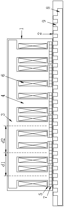
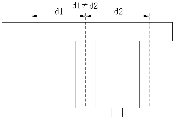
[0030] refer to Figure 1-9 , this specific embodiment adopts the following technical solutions: a linear motor with non-uniform teeth and magnetic tracks, including two parts of a mover 1 and a stator 2, and the mover 1 includes a mover yoke 3, a mover tooth 4, The mover tooth end 5, the winding 6 and the permanent magnet 7, the stator 2 includes the stator yoke 8 and the stator tooth 9, the mover teeth 4 connected with the mover yoke 3 are arranged non-uniformly in space, and the permanent magnet 7 is placed on the mover The stator teeth ends 5 , the windings 6 are placed in the slots formed by the mover teeth 4 , and the stator teeth 9 are connected to the stator yoke 8 .

[0031] It is worth noting that in order to increase the sine degree of...


PUM


Abstract

The invention discloses a linear motor with non-uniform teeth and without magnetic track, and relates to the technical field of a permanent-magnet linear motor. The linear motor comprises two parts comprising a rotor and a stator, wherein the rotor comprises a rotor yoke, rotor teeth, rotor tooth end parts, windings and permanent magnets, the stator comprises a stator yoke and stator teeth, the rotor teeth connected with the rotor yoke are arranged in a space in a non-uniform way, the permanent magnets are arranged at the rotor tooth end parts, the windings are arranged in grooves formed by the rotor teeth, and the stator teeth are connected to the stator yoke. The permanent magnets are not needed to be arranged on the stator, the linear motor is low in cost and is simple to install and transmit, and the motor is long in lifetime, small in electromagnetic interference and small in potential risk and has wide application prospect.

Description

technical field [0001] The invention relates to the technical field of permanent magnet linear motors, in particular to a linear motor with non-uniform teeth and no magnetic track. Background technique [0002] In recent years, with the rapid development of high-end machine tools, semiconductors, photovoltaics, laser cutting, liquid crystal panels, and lithium battery industries, there is an urgent need for high-speed, high-precision, long-stroke and long-life linear motion systems. Traditional sliding propulsion The system, due to its own inherent shortcomings, has been unable to meet the market demand. Because the linear motor directly uses the electromagnetic force generated by the moving stator as the propulsion force, it effectively solves the four major shortcomings of the sliding propulsion system. It is suitable for working conditions such as long stroke, high precision, high dynamic response, and long life. In recent years, it has become more and more popular in the...

Claims


Application Information

Patent Timeline
Patent Type & Authority Applications(China)
IPC IPC(8): H02K41/02
Inventor 不公告发明人
Owner SUZHOU SEIDAL INTELLIGENT TECH CO LTD
Why Eureka
Try Eureka