
Rolling Mill Hydraulic Reduction System

A technology of hydraulic pressing and rolling mill, which is applied in the components of fluid pressure actuation system, metal rolling stand, metal rolling mill stand, etc., can solve the problems of easy-wear valve core jamming, internal leakage, pressure fluctuation, etc.

Active Publication Date: 2021-04-20
EASTERN GANSU UNIVERSITY
View PDF7 Cites 0 Cited by
  • Summary
  • Abstract
  • Description
  • Claims
  • Application Information

AI Technical Summary

Problems solved by technology

[0003] In hot rolling mills and cold rolling mills, the servo hydraulic system of rolling mills is the most difficult and important point in the work of hydraulic technicians, and it is also the place where there are most failures, shutdowns, repairs and overhauls. It needs to overcome the requirements of high pressure, high temperature and high cleaning. The maintenance cost is high, especially the replacement cost of the pressing oil cylinder is 400,000-500,000 per piece. Now the average service life of the pressing oil cylinder on each rolling mill in our factory is about 2 years, and the cost of the servo valve is 50,000-60,000. / piece, the average service life of the servo valve on each rolling mill is about 1 year; in the production process, in addition to the equipment cost, there are also fluctuations in the rolling force due to failure of the servo valve and the failure of the pressing oil cylinder, and the thickness of the surface of the steel plate or steel strip. Inconsistency and broken belt phenomenon, resulting in product loss, reduced yield and other problems, in order to improve the service life of servo valves and rolling mills, reduce hydraulic system failures, reduce product loss, and increase yield, most of them use regular replacement of filter elements , replace the hydraulic oil regularly. However, during the process of equipment maintenance and point inspection and replacement of rubber hoses, sundries and particles are invisible brought into the hydraulic system. In the section of the pipeline, the hydraulic oil has not been filtered for a long time, resulting in sundries and particles remaining in the pipeline. The piston seal in the depressing oil cylinder rubs back and forth under high pressure, which is easy to wear and cause serious internal leakage, resulting in pressure fluctuations and rolling force. Fluctuations lead to uneven surface thickness of steel plates or strips and broken belts. The servo valve spool has very high requirements on the cleanliness of hydraulic oil. The service life is short and there are many faults, so the hydraulic system needs to be improved, which is conducive to improving the cleanliness of the hydraulic oil in the pipeline, reducing particle residue, and improving the service life of the servo valve and the pressing cylinder

Method used


Image

  • Rolling Mill Hydraulic Reduction System
  • Rolling Mill Hydraulic Reduction System
  • Rolling Mill Hydraulic Reduction System

Examples


Embodiment Construction

[0019] The preferred embodiments of the present invention will be described in detail below with reference to the accompanying drawings.

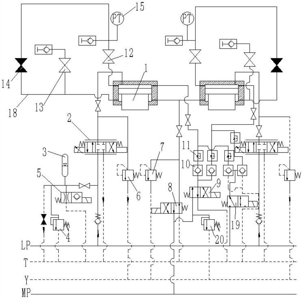
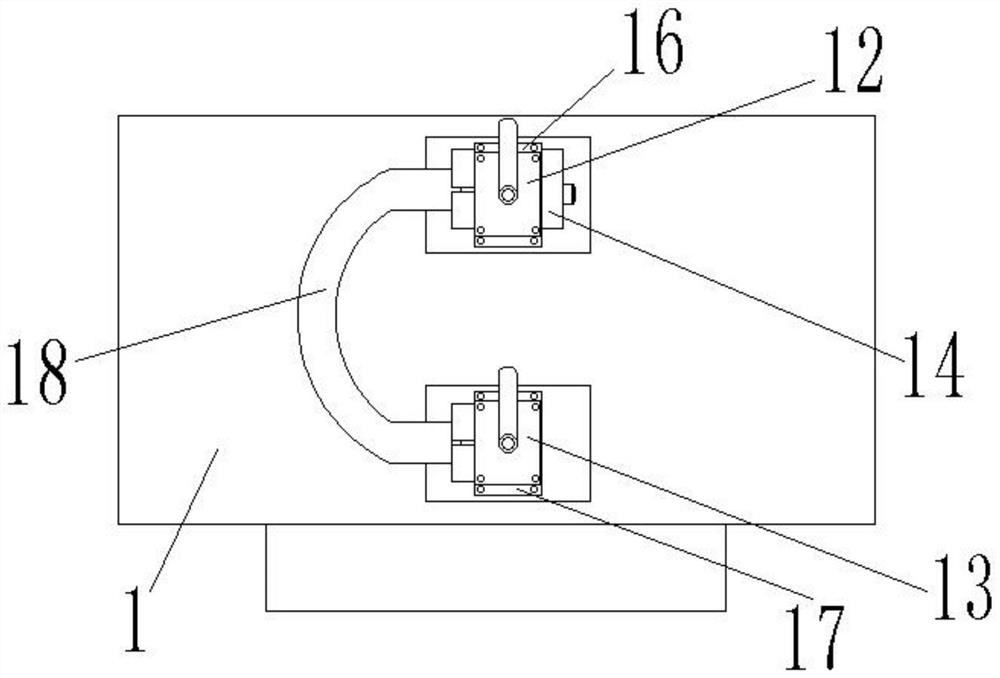
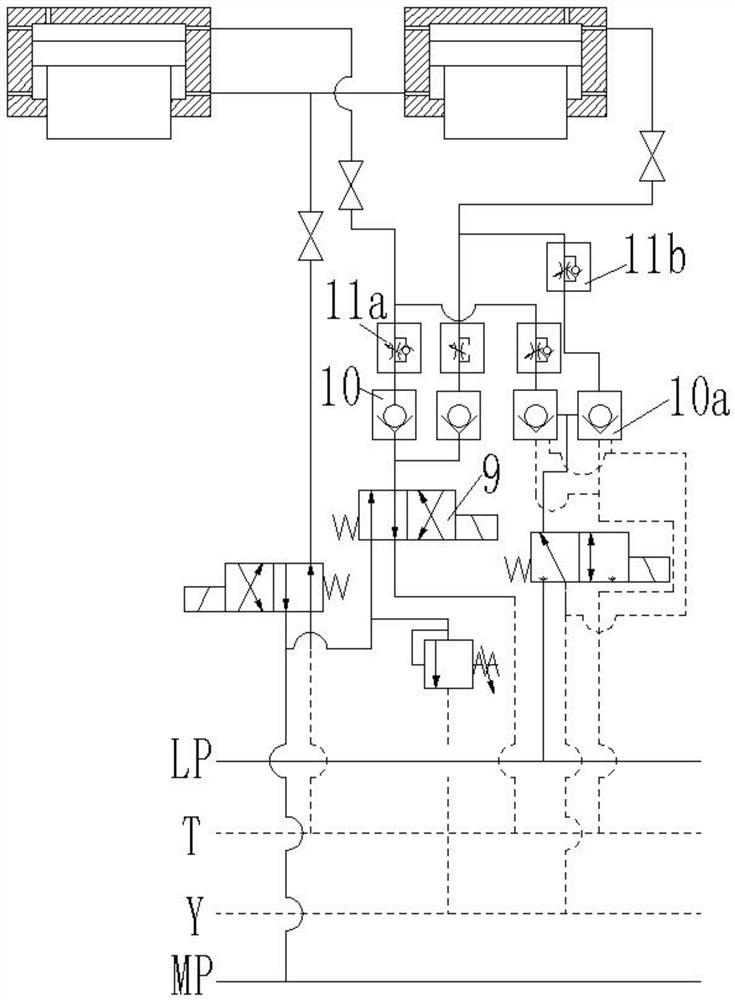
[0020] Such as Figure 1-3 Shown is a structural schematic diagram of the rolling mill hydraulic pressing system of the present invention; a rolling mill hydraulic pressing system of the present invention includes a pump station and a pair of oppositely arranged pressing cylinders 1, and the pump station is connected with a main oil supply high-pressure pipeline LP, the main oil supply medium pressure pipeline MP, the main oil return pipeline T, the main overflow pipeline Y, the quick discharge oil circuit and the circulation oil circuit, the main oil supply medium pressure pipeline MP is provided with a normally closed two One-position four-way electromagnetic reversing valve I8 and normally closed two-position four-way electromagnetic reversing valve II9, the normally closed two-position four-way electromagnetic reversing valve I8 and nor...


PUM


Abstract

The invention discloses a rolling mill hydraulic pressing system, which comprises a pumping station and a pressing oil cylinder. The pumping station is connected with a main oil supply high pressure pipeline, a main oil supply medium pressure pipeline, a main oil return pipeline, a main overflow pipeline, Quick discharge oil circuit and circulating oil circuit, the main oil supply medium pressure pipeline is in one-way communication with the rod chamber of the depression cylinder and the rodless chamber of the depression cylinder, and the main oil supply high pressure pipeline is in one-way communication with the rodless chamber of the depression cylinder , the circulating oil circuit communicates with the rod chamber of the pressing cylinder and the rodless chamber of the pressing cylinder at the same time, and a normally closed gate valve is arranged on the circulating oil circuit. One-way high-pressure oil flows in one direction to achieve one-way pressing and rolling, and the circulating oil circuit is used to connect the rodless chamber and the rod chamber of the pressing cylinder to realize oil circuit circulation, which is convenient for the hydraulic oil in the pressing cylinder to be replaced and circulated to filter, avoiding servo valves Slag stuck, to improve the cleanliness of the hydraulic oil in the pipeline, reduce particle residue, and improve the service life of the servo valve and the depressing cylinder.

Description

technical field [0001] The invention belongs to the technical field of hydraulic transmission, in particular to a rolling mill hydraulic pressing system. Background technique [0002] Hot plate rolling mills and thin plate cold rolling mills generally use electric pressing plus hydraulic pressing to provide rolling force. The electric pressing is designed with a long stroke, slow response and low adjustment accuracy, and is only used before rolling. Pre-swing roll gap; hydraulic pressure has short stroke, fast response, good anti-interference performance and high adjustment accuracy, which is suitable for real-time adjustment of roll gap during rolling; therefore, in hot rolling mills, rolling is mainly provided by hydraulic pressure. force to complete the rolling of the steel plate; a typical hydraulic pressing system consists of a PLC controller, a servo valve and a hydraulic cylinder; the electrical controller outputs a servo valve control signal (voltage or current signa...

Claims


Application Information

Patent Timeline
Patent Type & Authority Patents(China)
IPC IPC(8): F15B11/08F15B13/02F15B13/04F15B13/042F15B21/041F15B1/04B21B31/32
Inventor 敬谦李培武张帆
Owner EASTERN GANSU UNIVERSITY
Learn More