Polarization-state control optical switch based on surface plasmon super-surface

A polarization controller, a technology for controlling light, applied in the field of optical switches, can solve the problems of large size of optical switches, difficult device integration of micro-nano scale, and limitations in promotion and use, and achieves reduced size, simple structure, and good stability. Effect

Active Publication Date: 2019-06-18
ZHONGBEI UNIV
View PDF5 Cites 1 Cited by
  • Summary
  • Abstract
  • Description
  • Claims
  • Application Information

AI Technical Summary

Problems solved by technology

Traditional optical switches are large in size and have the problem of optical diffraction limit. It is difficult to integrate the device into the micro-nano scale, and the promotion and use are limited.

Method used


Image

  • Polarization-state control optical switch based on surface plasmon super-surface
  • Polarization-state control optical switch based on surface plasmon super-surface
  • Polarization-state control optical switch based on surface plasmon super-surface

Examples


Embodiment 1

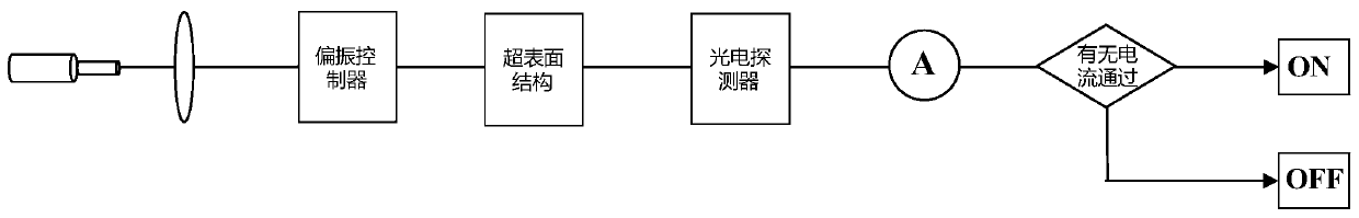
[0023] In order to solve the technical problems of large optical switch size and optical diffraction limit in the prior art, the embodiment of the present application provides a polarization state control optical switch based on surface plasmon metasurface, such as figure 1 As shown, including lasers, lenses, polarization controllers, metasurface structures, photodetectors and ammeters arranged in sequence, the lasers, lenses, polarization controllers and metasurface structures are located on the same axis, and the distance between the photodetectors and ammeters Electrical connection between.

[0024] in particular:

[0025] The lens, in this embodiment, is specifically a convex lens. The beam emitted by the laser is generally a radial conical beam, and the lens converges it into multiple parallel beams or a line beam, so that it can be better focused on the polarization controller.

[0026] The polarization controller, this embodiment is specifically a wave plate type polar...

Embodiment 2

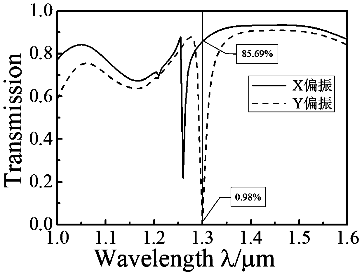
[0036] In order to further illustrate the different transmittances of the metasurface structure for X-direction polarized light and Y-direction polarized light in Example 1, this embodiment discloses the transmission characteristics of the metasurface structure for X-direction polarized light and Y-direction polarized light.

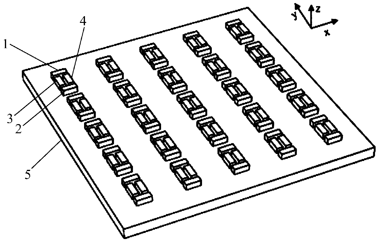
[0037] Such as figure 2 As shown, it is a polarization state control optical switch based on a surface plasmon metasurface in this embodiment. The period of each unit structure in the metasurface structure is 1200nm×1200nm, the thickness of the substrate 5 is 100nm, and the substrate 5 is SiO 2 The materials, the first rod body 1, the second rod body 2, the third rod body 3 and the fourth rod body 4 are exactly the same, all made of Au material, and the dimensions are:

[0038] 200nm long × 80nm wide × 50nm thick; the distance between the two ends of the third rod 3 from the first rod 1 and the second rod 2 is 40nm, and the distance between the third r...


PUM

PropertyMeasurementUnit
transmittivityaaaaaaaaaa
optical propertiesaaaaaaaaaa

Abstract

The invention relates to the technical field of optical switches, in particular to a polarization-state control optical switch based on a surface plasmon super-surface. The swtich comprises a laser, alens, a polarization controller, a super-surface structure, a photoelectric detector and an ampere meter that are connected successively. The laser emits a beam; the beam is projected to the polarization controller through the lens; the polarization controller receives the beam and outputs a first signal; the super-surface structure receives the first signal and outputs a second signal under excitation of the first signal; the photoelectric detector receives the second signal and outputs a signal to the ampere meter; and the state of the polarization-state control optical switch is determinedbased on the current of the ampere meter. On the basis of the super-surface structure, different transmission characteristics are generated under excitation of different polarized light; incident light passes selectively and a switching effect of incident light blocking or passing is realized; and the optical switch is turned on or off by changing the external conditions to affect the excitationand transmission characteristics of the surface plasmon of the super-surface structure.

Description

technical field [0001] The invention relates to the technical field of optical switches, in particular to a polarization state control optical switch based on a surface plasmon metasurface. Background technique [0002] With the development of optical information and optical communication, optical communication is developing into an integrated optical circuit, so the miniaturization of the size of optical devices is required. As the basic unit of information exchange and processing system, optical switch is of great significance to optical information and optical communication. Its function is to realize a certain parameter of the optical signal, such as power and phase, to change from one state to another state quickly and reversibly under the action of the control variable. Traditional optical switches are large in size and have the problem of optical diffraction limit. It is difficult to integrate the device into the micro-nano level, and the popularization and use are l...

Claims


Application Information

Patent Timeline
Patent Type & Authority Applications(China)
IPC IPC(8): G02F1/01G02B5/00
Inventor 张志东李刚张彦军张斌珍段俊萍
Owner ZHONGBEI UNIV
Why Eureka
Try Eureka