Dielectric waveguide filter

A dielectric waveguide and filter technology, applied in the field of dielectric waveguide filters, can solve problems such as poor product consistency, leakage of silver at the bottom of holes, and fluctuations.

Inactive Publication Date: 2019-06-18
GUANGDONG GOVA ADVANCED MATERIAL TECH
View PDF5 Cites 5 Cited by
  • Summary
  • Abstract
  • Description
  • Claims
  • Application Information

AI Technical Summary

Problems solved by technology

[0003] In the existing technology, such as figure 1 and figure 2 As shown, the dielectric block 100 includes a resonator 101, a resonator 102, and a coupling structure 104. The resonator 101 and the resonator 102 are connected through a capacitive coupling structure 104. A blind hole 103 is opened on the capacitive coupling structure 104. By controlling the blind hole The distance between 103 and the bottom of the resonator and the diameter of the blind hole 103 can adjust the capacitive coupling strength. In actual research and development and production, it is found that the above-mentioned dielectric waveguide filter has the following deficiencies: 1. The size of the capacitive coupling is from the blind hole 103 to the bottom of the resonator Distance control, the distance is very sensitive to the size of capacitive c

Method used


Image

  • Dielectric waveguide filter
  • Dielectric waveguide filter
  • Dielectric waveguide filter

Examples


Embodiment 1

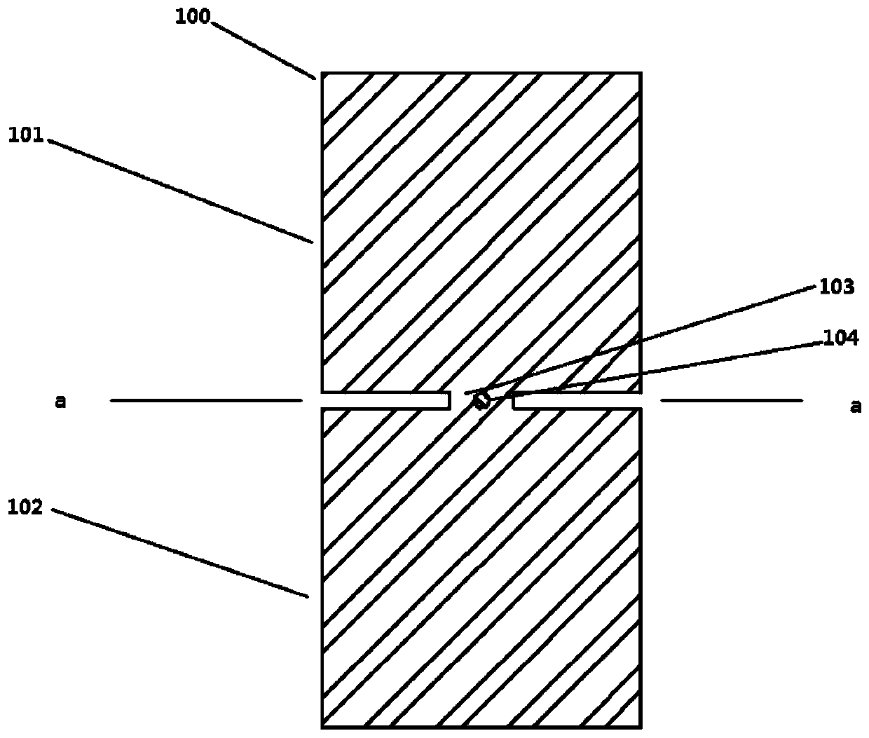
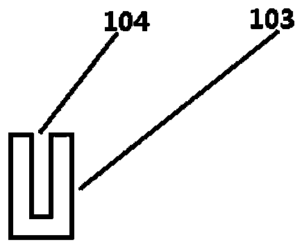
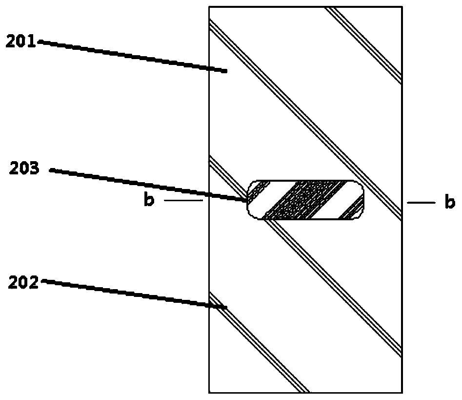
[0043] Embodiment 1 provides a solution including two dielectric resonators, such as image 3 with Figure 4 As shown, the dielectric waveguide filter includes a dielectric resonator 201 and a dielectric resonator 202 , the dielectric resonator 201 and the dielectric resonator 202 are connected through an H-shaped coupling structure 205 , and the H-shaped coupling structure 205 has deep grooves 203 and shallow grooves 204 .

[0044] In the above-mentioned embodiment, the length and width of the deep groove 203 and the shallow groove 204 are the same, the depth of the deep groove 203 exceeds half of the overall height of the H-shaped coupling structure 205, and the top, bottom and sides of the H-shaped coupling structure 205 are uniform. It is flush with the dielectric resonator 201 and the dielectric resonator 202 .

Embodiment 2

[0046] Different from Embodiment 1, the dielectric waveguide filter in Embodiment 2 includes four dielectric resonators, such as Figure 5 As shown, dielectric resonator 302, dielectric resonator 304, dielectric resonator 305, and dielectric resonator 306 are respectively, wherein, 301 is an input and output connector, and dielectric resonator 302 and dielectric resonator 304 are connected by a window-shaped coupling structure 303 forms the main coupling, between the dielectric resonator 304 and the dielectric resonator 305 and between the dielectric resonator 305 and the dielectric resonator 306 adopts the same coupling structure as the window-shaped coupling structure 303, between the dielectric resonator 302 and the dielectric resonator 306 Between, there is an H-shaped coupling structure 307, the dielectric waveguide filter can form a transmission zero at the high end of the passband and the low end of the passband, as can be seen from the figure, the window-shaped coupling...

Embodiment 3

[0048] The above two embodiments provide the situation of an even number of dielectric resonators. In the third embodiment, a situation of a dielectric waveguide filter including three dielectric resonators is provided, such as Image 6 As shown, the dielectric waveguide filter includes a dielectric resonator 402, a dielectric resonator 403 and a dielectric resonator 404, 401 is an input and output connector, and between the dielectric resonator 402 and the dielectric resonator 403 404 share the window-shaped coupling structure 406 to form the main coupling, and realize a window-shaped coupling structure to couple three sequentially. Between the dielectric resonator 402 and the dielectric resonator 404, there is an H-shaped coupling structure 405. The dielectric Waveguide filters can form a transmission zero at the low end of the passband.


PUM


Abstract

The invention discloses a dielectric waveguide filter which comprises a plurality of dielectric resonators, wherein at least two dielectric resonators are connected by an H-shaped coupling structure to form capacitive coupling; the H-shaped coupling structure comprises a structure main body; the structure main body is oppositely provided with a deep groove and a shallow groove; both sides of the H-shaped coupling structure are respectively connected with two dielectric resonators; the H-shaped coupling structure is simple in structure, low process requirements and easy to produce and debug; athickness of a middle part of the H-shaped coupling structure is decided by depths of two grooves together, and even though both sides of the H-shaped coupling structure are ground to different degrees, the thickness of the middle part is also not influenced, so that the thickness of the middle part is easier to control, consistency of the product is improved and meanwhile, the size of the capacitive coupling can be regulated by regulating widths of both the sides and the thickness of the middle of the H-shaped coupling structure; and relative to an existing blind hole, the deep groove and theshallow groove have the advantages of increase of openings, large area, contribution to reduction of the metallization process difficulty and convenience for batch production of the dielectric waveguide filter.

Description

technical field [0001] The invention relates to the technical field of communication equipment components, in particular to a dielectric waveguide filter. Background technique [0002] Compared with traditional metal waveguide filters, dielectric waveguide filters based on high dielectric constant ceramic materials have the advantages of compact size and higher Q value, but limited by the material characteristics of dielectric waveguide filters, generally in the design of filters When it is necessary to add a capacitive coupling structure to achieve transmission zero. [0003] In the prior art, such as figure 1 with figure 2 As shown, the dielectric block 100 includes a resonator 101, a resonator 102, and a coupling structure 104. The resonator 101 and the resonator 102 are connected through a capacitive coupling structure 104. A blind hole 103 is opened on the capacitive coupling structure 104. By controlling the blind hole The distance between 103 and the bottom of the...

Claims


Application Information

Patent Timeline
IPC IPC(8): H01P1/20
Inventor 何钟鑫肖利蒙黄伟杰龙志勇杨继聪
Owner GUANGDONG GOVA ADVANCED MATERIAL TECH
Why Eureka
Try Eureka