Mechanical release structure, implant and mechanical release instrument

An implant and mechanical technology, applied in the field of medical devices, can solve problems such as difficult and reliable release, and achieve the effect of reliable release, convenient operation, and stable interlocking

Pending Publication Date: 2019-06-21
苏州优医港科技有限公司
View PDF0 Cites 8 Cited by
  • Summary
  • Abstract
  • Description
  • Claims
  • Application Information

AI Technical Summary

Problems solved by technology

[0004] However, there are certain challenges in the release technology of existing embolic devices, and it is not easy to achieve reliable release

Method used


Image

  • Mechanical release structure, implant and mechanical release instrument
  • Mechanical release structure, implant and mechanical release instrument
  • Mechanical release structure, implant and mechanical release instrument

Examples


Embodiment 1

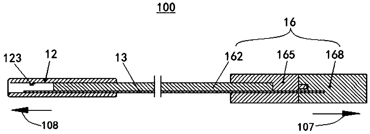
[0038] figure 1 A cross-sectional view of the mechanical release structure 100 provided in this embodiment, figure 2 is a schematic diagram of an implant 10 cooperating with a mechanical release structure 100, image 3 For the assembled sectional view of the mechanical release structure 100 and the implant 10, please refer to figure 1 , figure 2 and image 3 shown.

[0039] The mechanical release structure 100 provided in this embodiment 1 includes a release tube 12 and a release rod 13, the inner wall of the release tube 12 is provided with a protrusion, and the proximal end of the implant 10 is provided with a clamping part 103, and the clamping part 103 extends into the release tube 12, the notch 105 of the clamping part 103 cooperates with the protrusion on the inner wall of the release tube 12, and under the support of the release rod 13, the implant 10 and the release tube 12 are clamped and locked, and the release rod 13 is locked. After being pulled away from be...

Embodiment 2

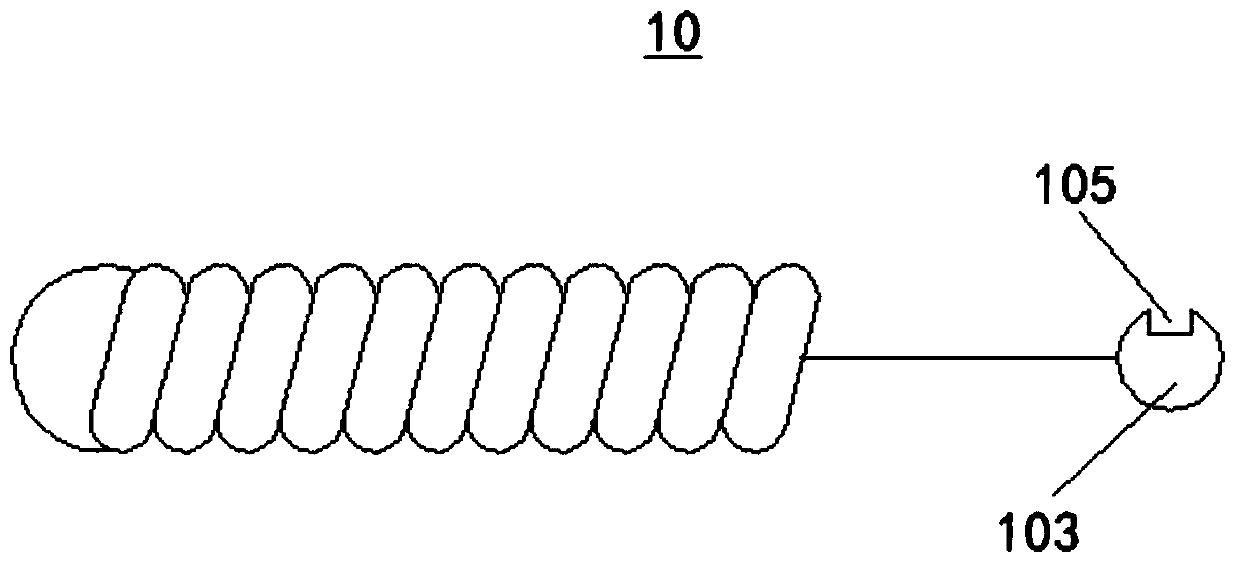
[0070] This embodiment provides an implant 10 configured to cooperate with a mechanical release structure 100, please refer to figure 2 As shown, the specific description is as follows.

[0071] The implant 10 is generally made of materials that are opaque to X-rays and have good biocompatibility, commonly used are platinum, tungsten, nickel-titanium or other alloy materials. When treating vascular diseases, the usual operation method is to insert the microcatheter into the blood vessel along the guide wire and reach the designated target area. After the microcatheter is in place, the implant 10 at the distal end of the delivery system can be pushed to the target area through the lumen of the microcatheter. After the position of the implant 10 is determined under the imaging technique, the implant 10 can be released from the delivery system so that it can be placed in the designated position.

[0072] The proximal end of the implant 10 is provided with a locking part 103 , ...

Embodiment 3

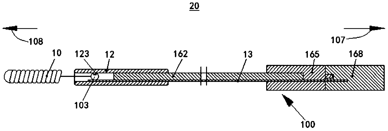
[0078]This embodiment provides a mechanical release device 20, including the implant 10 and the mechanical release structure 100 provided in Embodiment 1 above, please refer to image 3 As shown, the specific description is as follows:

[0079] The proximal end of the implant 10 is provided with a clamping portion 103, the clamping portion 103 is provided with a notch 105, the inner wall of the release tube 12 is protrudingly provided with a pin 123, the clamping portion 103 extends into the inner cavity of the release tube 12, and the concave The opening 105 can cooperate with the pin 123 , under the support of the release lever 13 , the clamping part 103 is lifted and can be clamped and locked with the release tube 12 .

[0080] When the release rod 13 is pulled under the action of an external force to separate the release rod 13 from the clamping portion 103, the notch 105 and the pin 123 of the release tube 12 are in a release state, thereby realizing the implant 10 and th...


PUM


Abstract

The invention discloses a mechanical release structure, an implant and a mechanical release instrument and relates to the technical field of medical instruments. The mechanical release structure matches the proximal end of the implant and comprises a release tube and a release rod, a clamping portion is arranged at the proximal end of the implant, the release tube is used for holding the clampingportion, and the distal end of the release rod is used for extending into an inner cavity of the release tube and matching the clamping portion. When the release rod is supported on the clamping portion, the clamping portion clamps the release tube to be in a locked state; when the release rod is separated from the clamping portion, the clamping portion and the release tube are in the release state. The mechanical release structure is ingenious in design, simple in structure, stable in interlocking, reliable in release and convenient to operate, and can repeatedly position the implant in a blood vessel rapidly, stably and accurately.

Description

technical field [0001] The invention relates to the technical field of medical devices, in particular to a mechanical release structure, an implant and a mechanical release device. Background technique [0002] The treatment of vascular diseases with minimally invasive intervention has gradually become the standard method. It is especially effective for diseases in locations where traditional surgical methods are at great risk, such as the treatment of aneurysms with embolic coils. [0003] Embolic coils are generally made of X-ray-opaque materials with good biocompatibility. When treating aneurysms, the usual method of operation is to insert the microcatheter into the blood vessel along the guide wire and reach the designated target area. After the microcatheter is in place, the embolic device (such as an embolic coil) at the distal end of the delivery system can be pushed to the target area through the lumen of the microcatheter. After the position of the embolization de...

Claims


Application Information

Patent Timeline
Patent Type & Authority Applications(China)
IPC IPC(8): A61B17/12
Inventor 黄正宗王吉刘文帅邓超郭丹赵转马晶晶管金谱汪令生李锋
Owner 苏州优医港科技有限公司
Why Eureka
Try Eureka