Robot for clearance measurement-compensation during composite assembly and clearance compensation method

A robot and gap technology, applied in the field of robots and gap compensation, can solve the problems of not finding robots, low degree of automation, relying on manual operation, etc., to achieve the effect of accurate three-dimensional shape of assembly gap, improve assembly efficiency, and reduce waste.

Active Publication Date: 2019-06-21
NANJING UNIV OF AERONAUTICS & ASTRONAUTICS
View PDF3 Cites 1 Cited by
  • Summary
  • Abstract
  • Description
  • Claims
  • Application Information

AI Technical Summary

Problems solved by technology

[0004] However, the gap compensation in composite material assembly relies heavily on manual operation, which is time-consuming and labor-intensive, and the degree of automation is low
The current research has not found a robot that can automatically measure the assembly gap and fill the liquid gasket

Method used


Image

  • Robot for clearance measurement-compensation during composite assembly and clearance compensation method
  • Robot for clearance measurement-compensation during composite assembly and clearance compensation method
  • Robot for clearance measurement-compensation during composite assembly and clearance compensation method

Examples


Embodiment 1

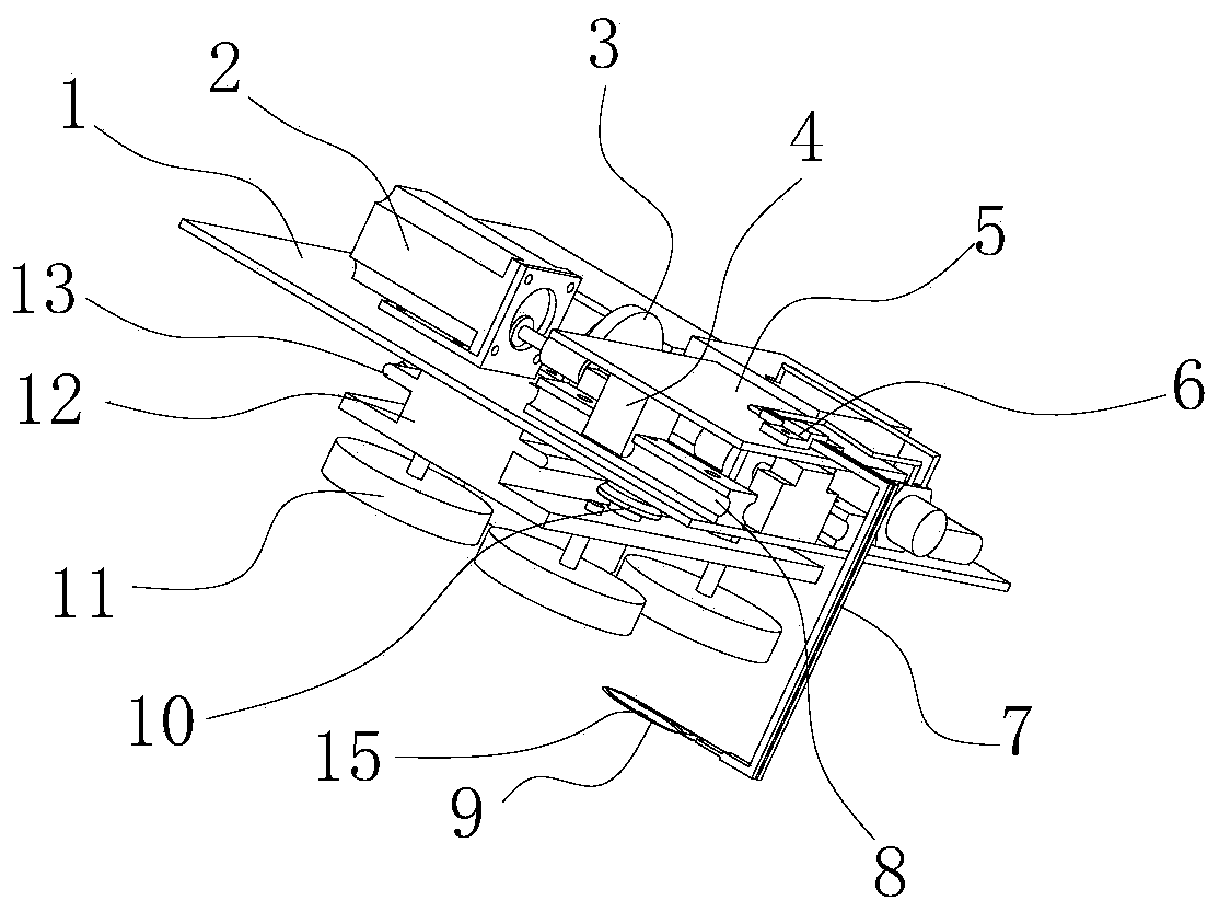
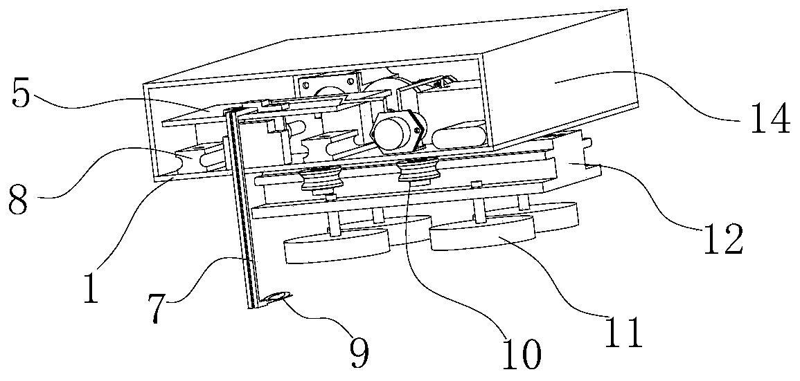
[0037] This embodiment is a robot for gap measurement-compensation in composite material assembly, such as figure 1 and figure 2 As shown, it consists of an integrated motion device, a gap measurement device, a gap compensation device and a control device.

[0038] The integrated motion device such as figure 1 , figure 2 and Figure 6 As shown, it includes a guide rail 12 and a chassis 1, the bottom of the guide rail 12 is fixed with a plurality of vacuum chucks 11, the two sides of the guide rail 12 are provided with strip-shaped flanges 13 along the length direction, and the bottom of the chassis 1 Two rows of rollers 10 are installed, the rollers 10 are provided with annular grooves matching the flanges 13, and the flanges 13 on both sides of the guide rail 12 are snapped into the two rows of rollers 10 so that the chassis 1 is attached to the On the guide rail 12; the top of the chassis 1 is installed with a geared motor 16 for driving the roller 10 to move along the...

Embodiment 2

[0045] In this embodiment, the gap compensation method of the composite material component of the robot is used in the first embodiment, and a composite material wing box is selected as the research object. The used wing box is as follows: Figure 8 Shown, comprise seven components such as front beam 26, rear beam, left rib, middle rib, right rib, upper wall plate and lower wall plate 25, connect by high lock bolt between each part. Among them, the front beam and the rear beam are both carbon fiber epoxy resin composite laminates, formed by a male mold, with a C-shaped cross section, and cured by an autoclave. The material of the three wing ribs is aluminum alloy, which is cut into the final shape by CNC machining. The upper and lower panels are composite laminates cured in an autoclave using a female mold. Due to the molding errors of the front and rear beams and the upper and lower panels, gaps are created between the mating surfaces of the panels and beams. In this exampl...


PUM


Abstract

The invention relates to a robot for clearance measurement-compensation during composite assembly and a clearance compensation method. The robot comprises four parts; an integrated motion device comprises a guiding rail and a chassis capable of moving along the guiding rail; a clearance measurement device comprises a moving pair formed by sliding rails and sliding blocks, a cantilever and a stepping motor for driving the sliding blocks to move along the sliding rails; the sliding rails are fixed to the chassis; the front end of the cantilever is fixedly connected with the sliding blocks; a clearance measurement head is mounted at the tail end of the cantilever; a clearance filling compensation device comprises a peristaltic pump, a liquid gasket storage box and a hose; and a control deviceis used for receiving the strain value measured by a strain gage and controlling the speed of the integrated motion device. The method includes the following four steps that the clearance measurementdevice is calibrated, liquid gaskets are prepared, the robot is mounted, and clearance measurement and clearance compensation are performed. By the aid of the robot and the clearance compensation method, automation of clearance measurement and clearance filling compensation operations for assembled structures of composites of aircrafts is realized, the labor intensity is reduced, and the assembling efficiency is improved.

Description

technical field [0001] The invention relates to a robot and a gap compensation method used for gap measurement and compensation in composite material assembly, belonging to the technical field of aircraft assembly. Background technique [0002] Composite materials have been widely used in modern aviation manufacturing industry due to their excellent mechanical properties. However, there are still some problems in the use of composite materials. For example, due to the limitation of the molding process, the molding accuracy of composite material components is not high, and the thickness direction error, flatness, and angle deviation are large. Composite materials use a large number of half molds, and the surface quality of the molded surface is high, but due to the flow of resin during the curing process, the difference in thermal expansion coefficient between fibers and resins, etc., the quality of the non-moulded surface is poor. The geometric errors formed during the mold...

Claims


Application Information

Patent Timeline
Patent Type & Authority Applications(China)
IPC IPC(8): B29C65/00
Inventor 岳烜德安鲁陵蔡跃波
Owner NANJING UNIV OF AERONAUTICS & ASTRONAUTICS
Why Eureka
Try Eureka