High-pressure plunger pump skid-mounting device for oilfield water injection

A technology of high-pressure plunger pump and oil field water injection, which is applied to the parts, pump components, pump control and other directions of the pumping device used for elastic fluid, and can solve the problems of large consumables, difficult disassembly, and long construction period of the prefabricated house. Achieve real-time monitoring of pipeline temperature and pressure, high risk sensitivity, and reduce construction costs

Active Publication Date: 2019-06-21
黄山君润油田装备制造有限公司
View PDF6 Cites 6 Cited by
  • Summary
  • Abstract
  • Description
  • Claims
  • Application Information

AI Technical Summary

Problems solved by technology

Due to the high pressure and water quality requirements for water injection, scattered oilfield surface engineering, less environmental damage, and convenient traffic requirements, the prefabricated house has many defects such as more consumables, low utilization rate, difficult disassembly, and long construction period.
In addition, the oil field is often faced with a high temperature and high pressure working environment during the mining process. The plunger pump will have defects such as loud noise and easy failure after working for a long time, which will affect the work progress; and the pressure and temperature instruments of the existing prefabricated houses require manpower for a long time. Check, the valve cannot be quickly controlled when a dangerous situation occurs, and the function of early warning and response to the dangerous situation is lacking
And because the medium pressure required for water injection is high, the vibration reduction and filtration of the equipment are difficult problems
These problems lead to unstable or unsafe operation of the equipment

Method used


Image

  • High-pressure plunger pump skid-mounting device for oilfield water injection
  • High-pressure plunger pump skid-mounting device for oilfield water injection
  • High-pressure plunger pump skid-mounting device for oilfield water injection

Examples


Embodiment Construction

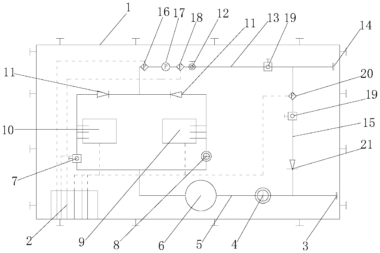
[0027] refer to Figure 1-6 , the present invention provides a technical solution: a high-pressure plunger pump skid-mounted device for oil field water injection, including a plunger pump unit 9 fixedly connected to a skid-mounted chassis 1, a plunger pump standby unit 10 and its matching pipeline, In addition, there is an explosion-proof electrical control cabinet 2; the adapter pipeline includes a liquid inlet pipe and a liquid outlet pipe, and a casing can also be provided outside. The device as a whole constitutes a mobile or even container-type skid-mounted device, which is convenient for disassembly and installation, and can be quickly transferred and reused, reducing the installation cost of the water injection pump room, and the setting of the standby unit avoids the easy failure of a single unit problems that hinder work.

[0028] A main liquid inlet valve 4 is arranged between the liquid inlet 3 of the liquid inlet pipeline and the plunger pump unit 9, and the downs...


PUM


Abstract

The invention relates to the field of oilfield water injection, and aims to provide a high-pressure plunger pump skid-mounting device for oilfield water injection. The high-pressure plunger pump skid-mounting device for oilfield water injection comprises a plunger pump unit fixedly connected onto a skid-mounting chassis, a plunger pump standby unit, an adaptive pipeline thereof, and an anti-explosion electric control cabinet, wherein the adaptive pipeline comprises a liquid inlet pipeline and a liquid outlet pipeline; the liquid inlet pipeline is provided with a liquid inlet main valve, a filter, a plunger pump control valve and a low-pressure pneumatic cut-off valve; high-pressure check valves are arranged on outlet pipelines of the plunger pump standby unit and the plunger pump unit; a pressure transmitter, a pressure gage and a first temperature transmitter are arranged on the liquid outlet pipe; and the anti-explosion electric control cabinet is connected with the low-pressure pneumatic cut-off valve, the plunger pump unit, the plunger pump standby unit, the pressure transmitter and the first temperature transmitter through leads. The plunger pump skid-mounting device is simplein structure, low in cost, capable of monitoring the pipeline temperature and the pressure in real time and conveniently and safely providing high-pressure water injection, and suitable for places with oilfields requiring water injection.

Description

technical field [0001] The invention relates to the field of oilfield water injection, in particular to a high-pressure plunger pump skid-mounted device for oilfield water injection. Background technique [0002] After the oil field is put into development, with the increase of production time, the energy of the oil layer itself will be continuously consumed, resulting in a continuous drop in the pressure of the oil layer, a large amount of degassing of the underground crude oil, an increase in the viscosity, a great reduction in the production of the oil well, and even the stop of spraying and production, resulting in underground A large amount of dead oil remains and cannot be recovered. In order to make up for the underground deficit caused by the extraction of crude oil, maintain or increase the pressure of the reservoir, achieve high and stable oil production, and obtain a high recovery rate, it is necessary to inject water into the oil field. For large-scale oilfield ...

Claims


Application Information

Patent Timeline
Patent Type & Authority Applications(China)
IPC IPC(8): F04B53/00F04B53/20F04B49/10E21B43/20
Inventor 方彦张军
Owner 黄山君润油田装备制造有限公司
Why Eureka
Try Eureka