A Blasting Vibration Meter Applied to Soft Soil

A vibrometer and soft soil technology, which is applied in the field of blasting vibrometers, can solve problems such as large data errors, low signal-to-noise ratio, and inability to accurately measure horizontal and vertical vibration waves.

Active Publication Date: 2021-04-20
广西隆太爆破工程有限公司
View PDF11 Cites 1 Cited by
  • Summary
  • Abstract
  • Description
  • Claims
  • Application Information

AI Technical Summary

Problems solved by technology

[0004] The installation structure of existing sensors in soft soil such as Figure 8 As shown, most of them insert the steel drill 20 into the ground, then install the top plate 19 on the end of the steel drill 20, coat the top plate with gypsum 21, and then install the sensor. Insert the steel drill 20 into the ground, and then fix it with gypsum 21. You need to carry the gypsum 21 and a water source. Because the sensor is very sensitive to temperature, and the gypsum 21 contains moisture, it is easy to affect the accuracy of the sensor measurement, and it takes time to wait for the gypsum 21 to solidify. , the solidified gypsum 21 adheres to the surface of the sensor, and it needs to be scraped off again with a blade. At the same time, when the sensor is measuring, after the building is blasted, the body wave propagating in the ground surface and the surface wave transmitted on the ground surface, body wave and surface wave When propagating, the nearby soft soil layer will be squeezed and deformed, causing the sensor to tilt, unable to accurately measure the horizontal and vertical vibration waves, resulting in errors in the measurement results of the tilted sensor, unable to accurately measure the explosion signal, and affecting the follow-up Work
[0005] The frequency tested by the existing blasting vibrometer is 10HZ ~ 300HZ, and the main vibration frequency after blasting is 2HZ ~ 200HZ, and the main frequency is lower as the blasting scale is larger (the main vibration frequency is 0.5HZ ~ 5HZ) The working principle of the existing vector sensor is as follows Figure 9 As shown, when the blasting of the building starts, it drives the nearby ground to vibrate, then drives the base to vibrate, and then drives the mass block 23 to move. Within the working frequency range of the sensor, it is bounced by the spring piece 25, and then the coil 24 and the magnet 22 move relative to each other. , cutting the lines of magnetic force, and generating an induced voltage in the coil 24, the output signal can be generated. When the blasting vibrometer is in use, it can only detect values ​​within the frequency range. The numerical calculation formula of the blasting vibrometer sensor is: g is the acceleration constant, m is the mass block, k is the elastic coefficient of the spring, and wo is the natural angular frequency. When fo is 1HZ, the relative displacement reaches 25cm, which is affected by the volume of the sensor. Within the frequency range of 1HZ, blasting vibration measurement The output signal of the instrument is extremely weak, the signal-to-noise ratio is low, and the vibration data generated by blasting cannot be accurately tested. As a result, the scope and vibration of the blasting cannot be estimated, the safety range cannot be determined, and the data error is large, which in turn affects the follow-up work.

Method used


Image

  • A Blasting Vibration Meter Applied to Soft Soil
  • A Blasting Vibration Meter Applied to Soft Soil
  • A Blasting Vibration Meter Applied to Soft Soil

Examples


Embodiment Construction

[0024] The following will clearly and completely describe the technical solutions in the embodiments of the present invention with reference to the accompanying drawings in the embodiments of the present invention. Obviously, the described embodiments are only some, not all, embodiments of the present invention. Based on the embodiments of the present invention, all other embodiments obtained by persons of ordinary skill in the art without making creative efforts belong to the protection scope of the present invention.

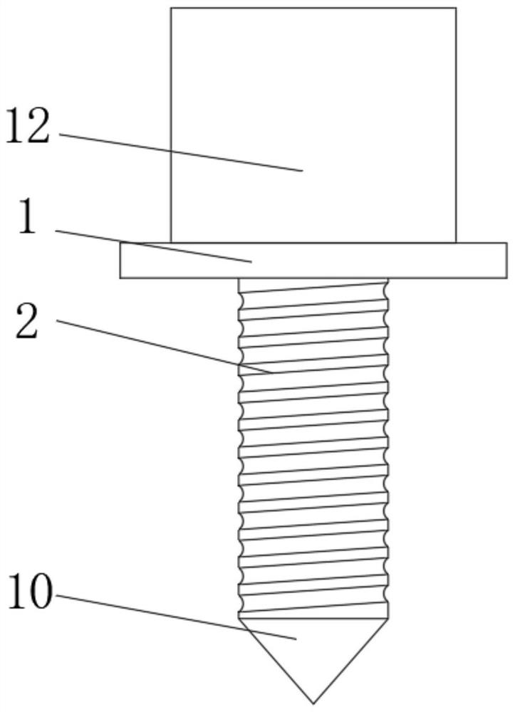
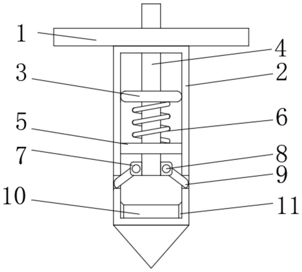
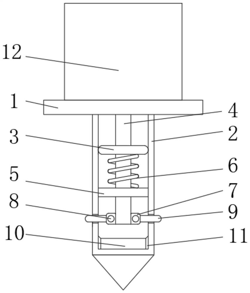
[0025] see Figure 1-7 , a blasting vibrometer applied to soft soil, comprising a support plate 1, a threaded rod 2, an induction housing 12, the threaded rod 2 is welded on the bottom of the support plate 1, the induction housing 12 is installed on the support plate 1, and the threaded rod 2 and the support plate 1 are welded to increase the stability of the connection between the threaded rod 2 and the support plate 1. The support plate 1 is made of cast ste...


PUM


Abstract

The invention relates to the field of intelligent manufacturing technology, and discloses a blasting vibrometer applied to soft soil, including a support plate, a threaded rod, and an induction shell, the threaded rod is welded on the bottom of the support plate, and the induction shell is installed on the support plate. Through the combined use of the first magnet and the second magnet, the spring part inside the sensor is directly removed, so that when the sensor is in use, through the mutual repulsion of the two magnets, the magnetic force is used instead of the elastic force, and the distance between the two magnets is adjusted. Adjust the size of the elastic strength, thereby changing the natural frequency of the blasting vibrometer, so that the blasting vibrometer can accurately detect vibration signals when used at low frequencies. On the one hand, it solves the problem that the blasting vibrometer cannot detect low-frequency signals. On the one hand, it solves the energy loss of the spring during use, and further solves the phenomenon that the elastic strength of the spring decreases during use, so that the elastic components inside the blasting vibrometer can always maintain a better state.

Description

technical field [0001] The invention relates to the technical field of intelligent manufacturing, in particular to a blasting vibrometer applied to soft soil. Background technique [0002] The blasting vibrometer is a portable special device for long-term on-site collection, recording and storage of blasting vibration and impact signals. It is mainly used to monitor the signals generated during blasting. [0003] The blasting vibration meter is mainly composed of a vector sensor and a host. The vector sensor receives the vibration signal and transmits it to the host. When the vector sensor is detecting, it needs to be rigidly connected with the object under test to ensure that the sensor can accurately detect the vibration signal. The instrument has the following problems during use; [0004] The installation structure of existing sensors in soft soil such as Figure 8 As shown, most of them insert the steel drill 20 into the ground, then install the top plate 19 on the end...

Claims


Application Information

Patent Timeline
Patent Type & Authority Patents(China)
IPC IPC(8): G01N3/313G01N29/04G01N29/26
Inventor 不公告发明人
Owner 广西隆太爆破工程有限公司
Why Eureka
Try Eureka