Capacitive sensor based on resonant frequency measurement and working method and application thereof

A capacitive sensor and resonant frequency technology, applied in the field of sensor measurement, can solve the problems of low signal-to-noise ratio, limited application range, large signal distortion, etc., and achieve the effect of high signal-to-noise ratio and high-bandwidth signal-to-noise ratio

Active Publication Date: 2019-06-21
北京同创微纳科技有限公司
View PDF5 Cites 4 Cited by
  • Summary
  • Abstract
  • Description
  • Claims
  • Application Information

AI Technical Summary

Problems solved by technology

Another common method is to measure the entire period of the signal. However, as the signal period changes, the sampling frequency also changes, resulting in large distortion of the signal obtained by the subsequent system, low signal-to-noise ratio, and limited application range.

Method used


Image

  • Capacitive sensor based on resonant frequency measurement and working method and application thereof
  • Capacitive sensor based on resonant frequency measurement and working method and application thereof
  • Capacitive sensor based on resonant frequency measurement and working method and application thereof

Examples


Embodiment Construction

[0038] The present disclosure will be further described below in conjunction with the accompanying drawings and embodiments.

[0039] It should be noted that the following detailed description is exemplary and intended to provide further explanation of the present disclosure. Unless defined otherwise, all technical and scientific terms used herein have the same meaning as commonly understood by one of ordinary skill in the art to which this disclosure belongs.

[0040] It should be noted that the terminology used herein is only for describing specific embodiments, and is not intended to limit exemplary embodiments according to the present disclosure. As used herein, unless the context clearly dictates otherwise, the singular is intended to include the plural, and it should also be understood that when the terms "comprising" and / or "comprising" are used in this specification, they mean There are features, steps, operations, means, components and / or combinations thereof.

[00...


PUM


Abstract

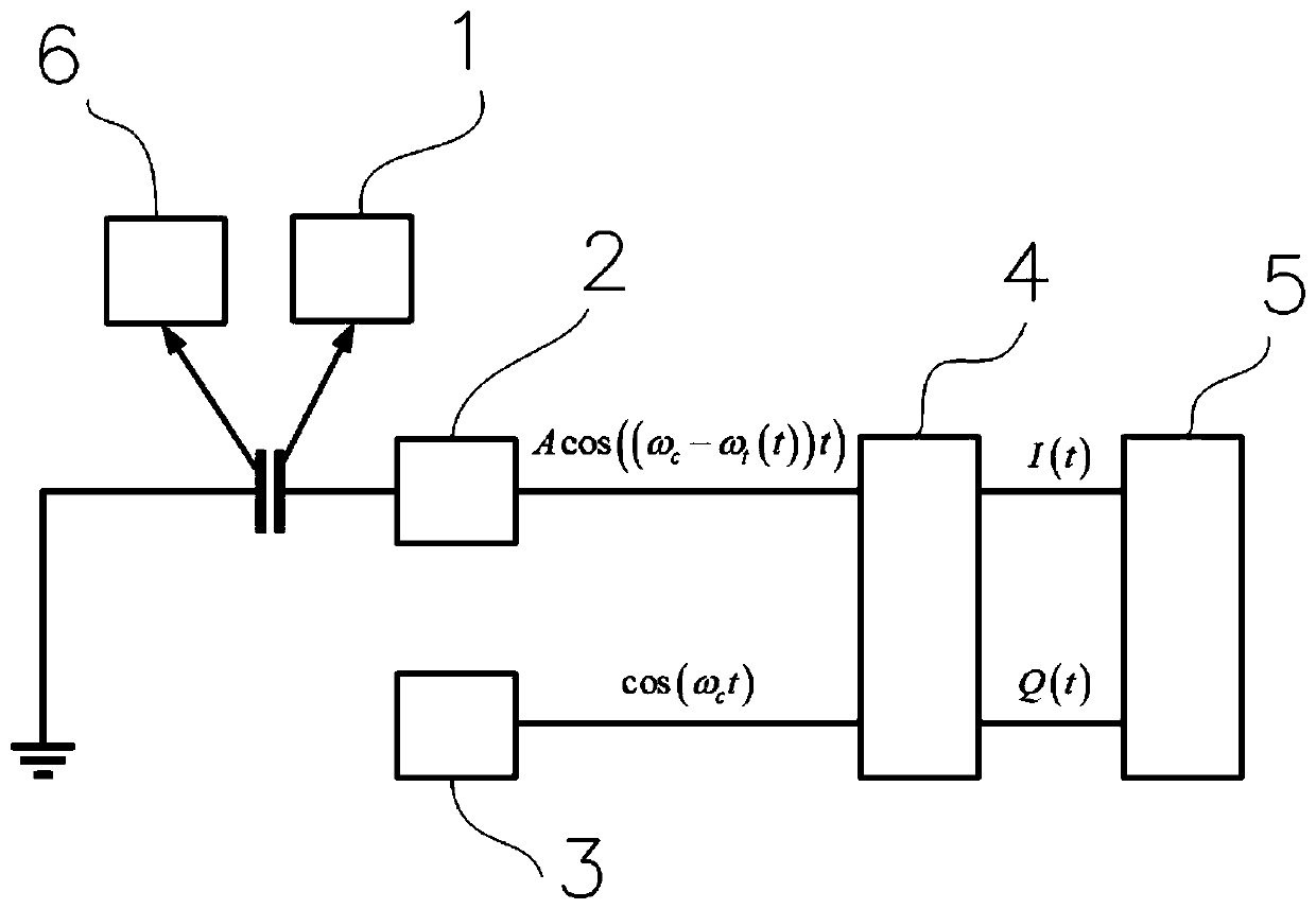
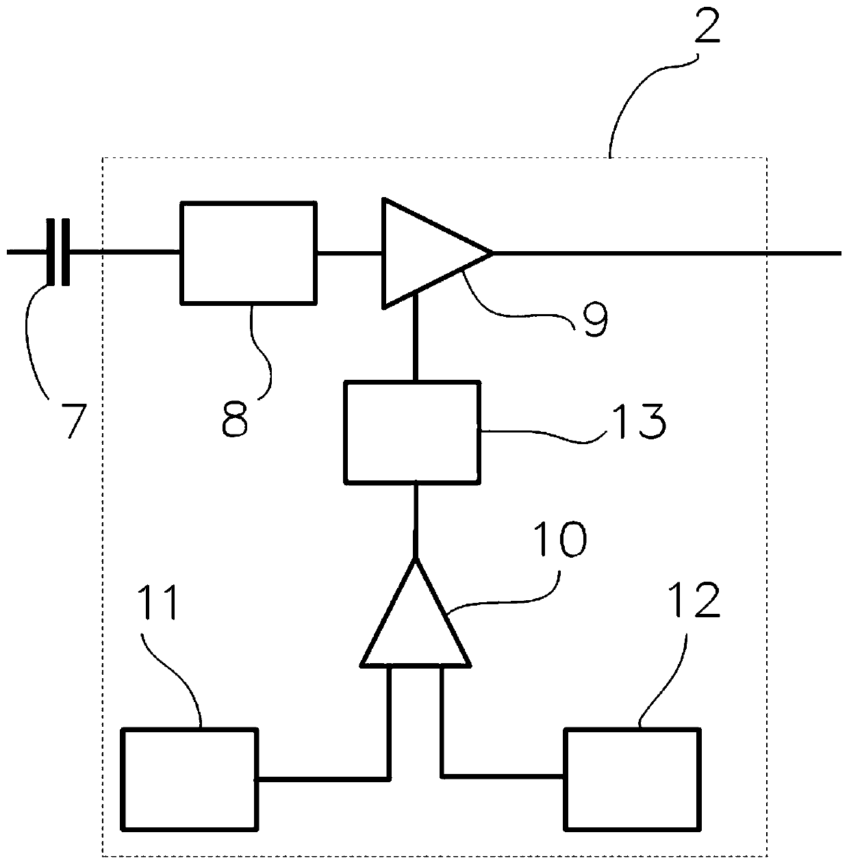
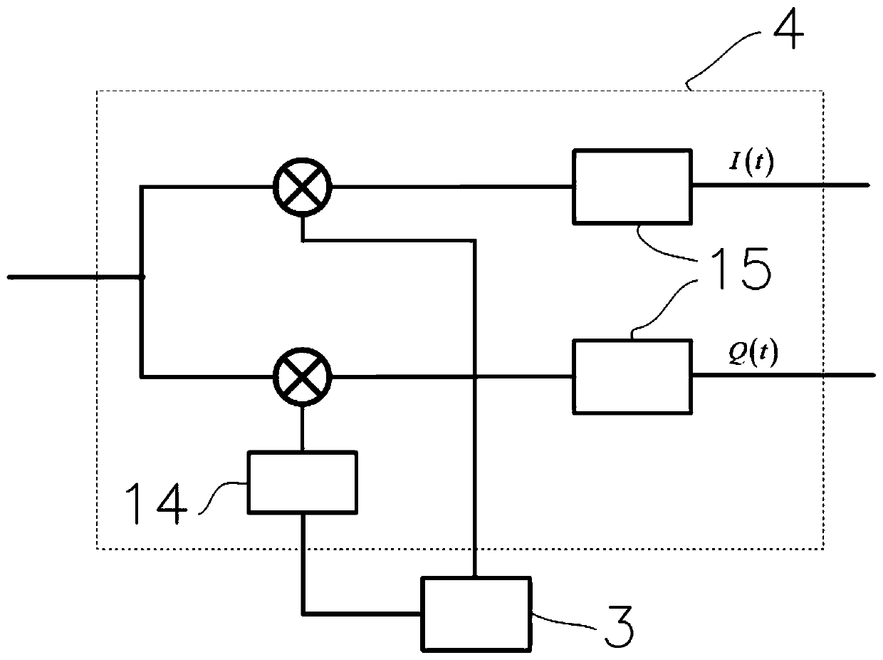
The invention provides a capacitive sensor based on resonant frequency measurement and a working method and an application thereof. The capacitive sensor includes a sensor probe forming a flat capacitor together with a detected pole plate, an equal amplitude frequency stabilizing sinusoidal oscillator connected with a probe end of the flat capacitor, an equal amplitude frequency stabilized sinusoidal oscillator, a local oscillator used for outputting amplitude and frequency-stable local oscillator signals, an orthogonal demodulator used for demodulating an oscillating signal into an in-phase component and an orthogonal component through the local oscillator signal, and an orthogonal phase measuring device used for calculating an inverse tangent function of the orthogonal component and thein-phase component to obtain the phase and the frequency of a frequency difference signal, wherein a detected pole plate end of the flat capacitor is grounded, the equal amplitude frequency stabilizedsinusoidal oscillator is used for outputting an oscillating carrier signal with the stable amplitude and the frequency offset corresponding to the displacement amount or the area change amount of thedetected pole plate, and the displacement amount or the area change amount of the detected pole plate is obtained based on the relationship between the frequency of the frequency difference signal and the capacitance change amount. The capacitive sensor is advantaged in that precise measurement can be achieved in a quite wide range of sampling frequencies.

Description

technical field [0001] The disclosure belongs to the field of sensor measurement, in particular to a capacitive sensor based on resonant frequency measurement and its working method and application. Background technique [0002] The statements in this section merely provide background information related to the present disclosure and may not necessarily constitute prior art. [0003] Capacitive displacement sensors have the characteristics of simple structure, high precision, good dynamic characteristics, and wide frequency range. They are often used to measure small displacements and have been widely used in industrial production and scientific research. [0004] The inventor found that the current capacitive sensor generally measures the resonant frequency by accumulating the number of signal zero crossings for a certain period of time, and inevitably there is a phase error between the initial phase error and the last zero crossing point to the end of the measurement time,...

Claims


Application Information

Patent Timeline
IPC IPC(8): G01R23/12G01B7/02
Inventor 陈志龙
Owner 北京同创微纳科技有限公司
Why Eureka
Try Eureka