Cable buffer layer conductivity defect detection method

A technology for electrical conductivity and defect detection, applied in the direction of testing dielectric strength, fault location, etc., can solve problems such as the inability to effectively connect the outer semi-conductive shield and the metal sheath, the narrow application range, and the inability to meet the performance testing of power cables. Detect the effect of efficient and simple method

Active Publication Date: 2019-06-21
GUANGDONG POWER GRID CO LTD +2
View PDF8 Cites 8 Cited by
  • Summary
  • Abstract
  • Description
  • Claims
  • Application Information

AI Technical Summary

Problems solved by technology

X-ray detection is to use X-rays to check the number and diameter of copper wires in the insulating gold cloth of the cable buffer layer. It is difficult to effectively reflect the situation of the entire cable and detect the condition of the entire cable through local sampling detection. the cable
In addition, the conductivity of the cable buffer layer is not only related to the number and diameter of copper wires, but also related to the weaving process of the gold cloth and the thickness of the fiber layer. When the number and diameter of copper wires meet the requirements, there are also copper wires In case of being hidden in the fibers without effective communication between the outer semi-conductive shield and the metal sheath
Partial discharge detection is to judge whether the insulation is damaged by detecting the partial discharge signal sent after the insulation is damaged. It cannot directly detect the conductivity of the cable buffer layer. The strength of partial discharge has no necessary relationship with the conductivity of the cable buffer layer. The method is not effective
[0004] The above method has the disadvantages of complex detection, narrow scope of application, and low effectiveness, and cannot meet the requirements of power cable performance detection.

Method used


Image

  • Cable buffer layer conductivity defect detection method
  • Cable buffer layer conductivity defect detection method
  • Cable buffer layer conductivity defect detection method

Examples


Embodiment 1

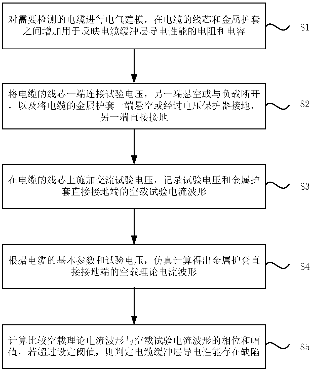
[0023] Please refer to the attached figure 1 , which is a schematic flowchart of a method for detecting a defect in the electrical conductivity of a cable buffer layer provided in Embodiment 1 of the present invention. The method specifically includes the following steps:

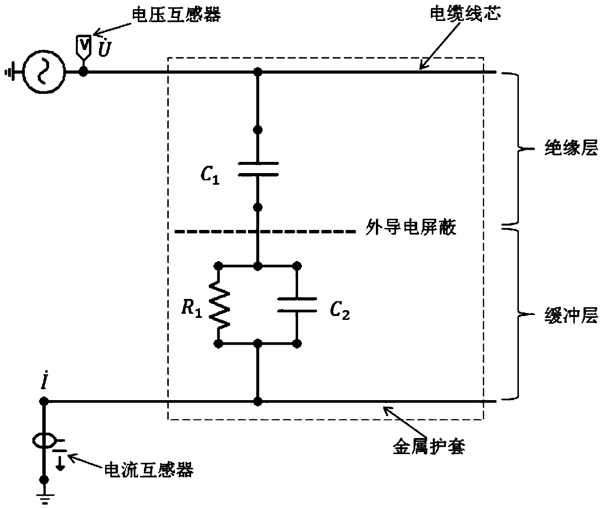
[0024] S1. Perform electrical modeling on the cable to be detected, and add resistance and capacitance between the cable core and the metal sheath to reflect the conductivity of the cable buffer layer.

[0025] It should be noted that the cable to be detected in this embodiment may be a cross-linked polyethylene (XLPE) cable. This embodiment is aimed at a single-core XLPE cable, which is mainly composed of a core, an inner semiconductive shielding layer, an insulating layer, an outer semiconductive shielding layer, a buffer layer, a metal sheath and an outer sheath. The copper wire in the buffer layer is connected to the outer conductive shield and the metal sheath, and there is no potential difference bet...


PUM


Abstract

The invention discloses a cable buffer layer conductivity defect detection method which comprises steps of electrically modeling a cable, disposing a resistor and capacitor between the wire core and the metal sheath of the cable to be detected, connecting one end of the wire core to test voltage, suspending the other end of the wire core or disconnecting the other end of the wire core from a load,suspending one end of the metal sheath or grounding the one end of the metal sheath through a voltage protector, and directly grounding the other end of the metal sheath; applying an AC test voltageto the wire core of the cable, and recoding the test voltage and the no-load test current waveform of the directly grounded end of the metal sheath; according to the basic parameters of the cable andthe test voltage, calculating the no-load theoretical current waveform of the directly grounded end of the metal sheath; comparing the phase and the amplitude of the no-load theoretical current waveform with those of the no-load test current waveform, and determining that the cable buffer layer has a conductivity defect if a set threshold is exceeded. The cable buffer layer conductivity defect detection method detects the entire cable, is simple and high in efficiency, and solves the inability to detect the cable in operation.

Description

technical field [0001] Embodiments of the present invention relate to the technical field of electric power engineering applications, and in particular to a method for detecting defects in the electrical conductivity of a cable buffer layer. Background technique [0002] XLPE power cables have been widely used in power systems, especially in areas with limited overhead line corridors such as cities and suburbs. Power cable faults have an increasing impact on power systems and economic society. In recent years, there have been many failures in China due to the discharge and burning of the outer semiconductive layer of the cable. The reasons are mainly due to the unqualified conductivity of the semiconductive buffer layer and the improper gap between the corrugated aluminum sheath, etc. The problem causes a potential difference between the outer semiconductive layer of the cable and the metal sheath, and the outer semiconductive layer or semiconductive buffer layer of the cab...

Claims


Application Information

Patent Timeline
IPC IPC(8): G01R31/08G01R31/12
Inventor 朱文卫王向兵梁爱武王彦峰张章亮邓小玉雷翔胜吴小蕙陈锟潘柏崇郭金根车伟娴刘明李嘉杰王兴华
Owner GUANGDONG POWER GRID CO LTD
Why Eureka
Try Eureka