Non-contact laser precise cylindrical gear profile radial eccentricity detection method

A cylindrical gear, non-contact technology, applied in the field of non-contact laser precision detection of radial eccentricity of cylindrical gear tooth profile, can solve the problems of affecting measurement accuracy, high cost, cumbersome work, etc., to achieve accurate measurement results, reduce economic costs, and detect Efficient effect

Inactive Publication Date: 2019-06-25
JILIN UNIV
View PDF0 Cites 4 Cited by
  • Summary
  • Abstract
  • Description
  • Claims
  • Application Information

AI Technical Summary

Problems solved by technology

Conventional gear eccentricity detection methods are mostly contact-type. The common ones are inter-tooth roller clamping dial indicator measurement and high-precision non-eccentricity matching for standard gear meshing measurement. The former detection is mainly based on manual reading and manual calculation, which takes a long time. In addition, it is easy to fatigue, easy to make mistakes, and the work is quite cumbersome, time-consuming and laborious; the latter standard gear must have a strict one-to-one correspondence with the parameters of the tested gear, and different tested gears need to be replaced with different standard gears for testing, which is costly. It is a contact measurement, which will inevitably cause wear problems and affect the measurement accuracy

Method used


Image

  • Non-contact laser precise cylindrical gear profile radial eccentricity detection method
  • Non-contact laser precise cylindrical gear profile radial eccentricity detection method
  • Non-contact laser precise cylindrical gear profile radial eccentricity detection method

Examples


Embodiment Construction

[0015] The present invention will be further described below in conjunction with accompanying drawing:

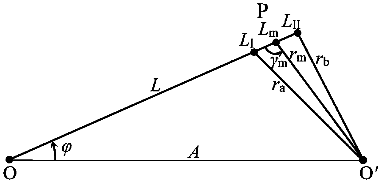
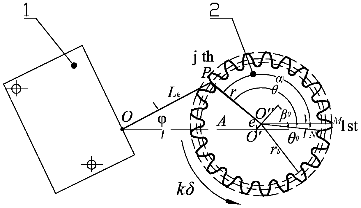
[0016] In order to adapt to the specific range L∈[L of the laser displacement sensor a , L b ], the measurement accuracy should satisfy the limit of the angle between the laser line and the normal line of the tooth profile |ξ|max , to avoid the excessively large measurement area caused by the slender laser beam spot covering the tooth profile, and to reduce the measurement error caused by the incident angle of the laser, the relative placement position A and A of the laser displacement sensor and the measured gear Strict optimization is definitely required.

[0017] Such as figure 1 , figure 2 As shown, the range of A is r a ~ L b + r a , The range is 0~arcsin(r a / A), r a is the radius of the addendum circle, r b is the radius of the base circle. Using the numerical calculation technology of the tooth profile curve, the angle between the laser line correspond...


PUM


Abstract

The invention relates to a non-contact laser precise cylindrical gear profile radial eccentricity detection method. A numerical value optimization model is established according to the range of a laser displacement sensor, the included angle between laser light and a profile normal line and other factors, the best installation position and the angle of the sensor are further obtained, and the problems that the detection precision is influenced due to elongation of a laser spot and an over large measuring angle can be avoided. The laser light is struck on a measured profile, the gear rotates ata constant speed around a rotation center, and data of each measured point of a single-sided profile of the gear are further measured. The installation angle of the sensor is adjusted, and in the same way, the data of each measured point of the profile at the other side of the gear can be measured. The data measured under two attitudes of the sensor are fused, processing is carried out based on the geometric relationship between the sensor and the gear: based on least squares linear regression, the initial calculation values of the gear profile radial eccentricity and the initial eccentric angle are obtained; and by using iterative cycle approximation of a Jacobian gradient matrix, the exact solutions of the gear profile radial eccentricity and the initial eccentric angle can be obtained.

Description

technical field [0001] The invention belongs to the field of radial eccentricity detection of a cylindrical gear tooth profile, and in particular relates to a non-contact laser precision detection method for a cylindrical gear tooth profile radial eccentricity. Background technique [0002] Gears are widely used in mechanical devices and industrial equipment, and are one of the key basic elements in modern transmissions. With the rapid development of contemporary industrial technology, the design, manufacture and testing level of gears has always been a hot issue in the engineering field. Gear manufacturing technology restricts the development of industrial machinery and is the key basic technology for the country's advanced industrial manufacturing. [0003] In the process of manufacturing, installation and operation, the gear shaft and gear cannot avoid bending deformation and radial eccentricity (circular runout of the ring gear). Gear eccentricity will cause vibration,...

Claims


Application Information

Patent Timeline
Patent Type & Authority Applications(China)
IPC IPC(8): G01B11/27
Inventor 裴永臣谢海量李皓关景晗徐龙夏峥嵘
Owner JILIN UNIV
Why Eureka
Try Eureka