Circuit board conveying structure and electroplating equipment
What is AI technical title?
AI technical title is built by Patsnap AI team. It summarizes the technical point description of the patent document.
A technology of electroplating equipment and circuit boards, which is applied in the direction of conveyors, conveyor objects, lighting and heating equipment, etc., can solve problems such as circuit board surface wrinkles, achieve uniform thickness of electroplating layer, and prevent wrinkles
Pending Publication Date: 2019-06-28
KUNSHAN DONGWEI MACHINERY CO LTD
View PDF1 Cites 3 Cited by
Summary
Abstract
Description
Claims
Application Information
AI Technical Summary
This helps you quickly interpret patents by identifying the three key elements:
Problems solved by technology
Method used
Benefits of technology
Problems solved by technology
[0005] Therefore, the technical problem to be solved by the present invention is to overcome the hysteresis of the lower end of the circuit board relative to the upper end of the circuit board when the circuit board conveying mechanism in the prior art transports the circuit board, which in turn causes the board surface of the circuit board after the circuit board is electroplated. There are wrinkles, so as to provide a circuit board conveying structure and its electroplating equipment
Method used
Image
Click on the blue label to locate the original text in one second.
Reading with bidirectional positioning of images and text.
Examples
specific Embodiment approach
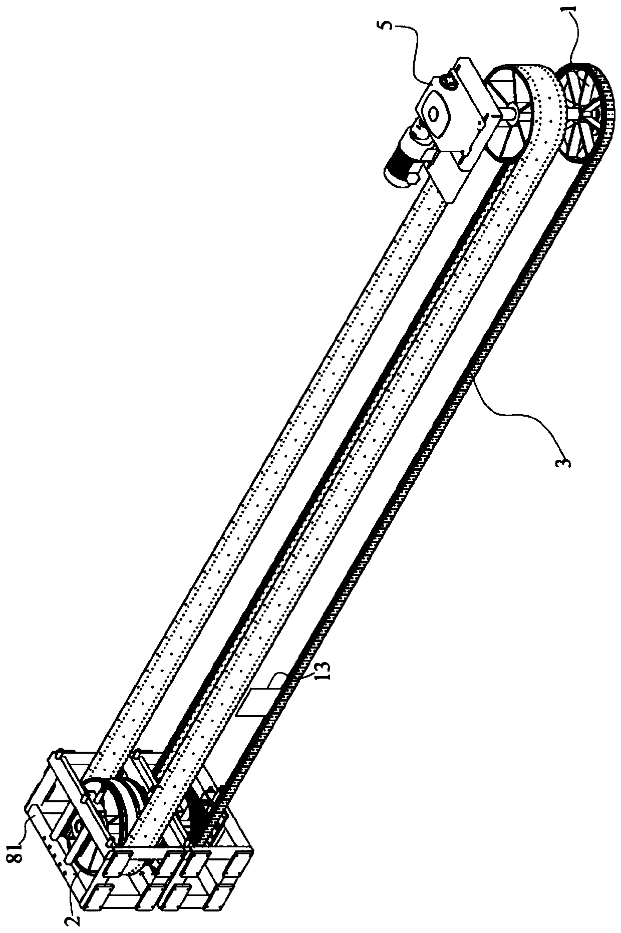
[0060] Such as Figure 1 to Figure 4 A specific implementation of the conveying structure of the circuit board shown includes:
[0061] The first transmission mechanism.
[0062] The second transmission mechanism is arranged parallel to each other in the vertical direction with the first transmission mechanism.
[0063] At least one clamp is arranged on the first transmission mechanism for clamping the upper end of the circuit board 13 and can move synchronously with the first transmission mechanism driven by the first transmission mechanism.
[0064] At least one material clip 4 is arranged on the second transmission mechanism and below the corresponding clamps, and is used to clamp the lower end of the circuit board 13, and can be driven by the second transmission mechanism with the The second transmission mechanism moves synchronously, and the running speed of the clamp is the same as that of the material clip 4 .
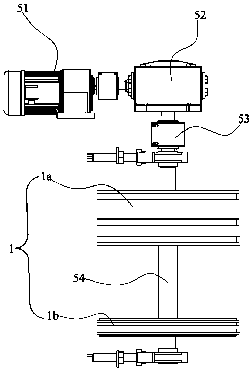
[0065] The driving mechanism 5 is connected with the fi...
Embodiment 2
[0078] Such as Figure 1 to Figure 7 A specific implementation of the shown electroplating equipment includes:
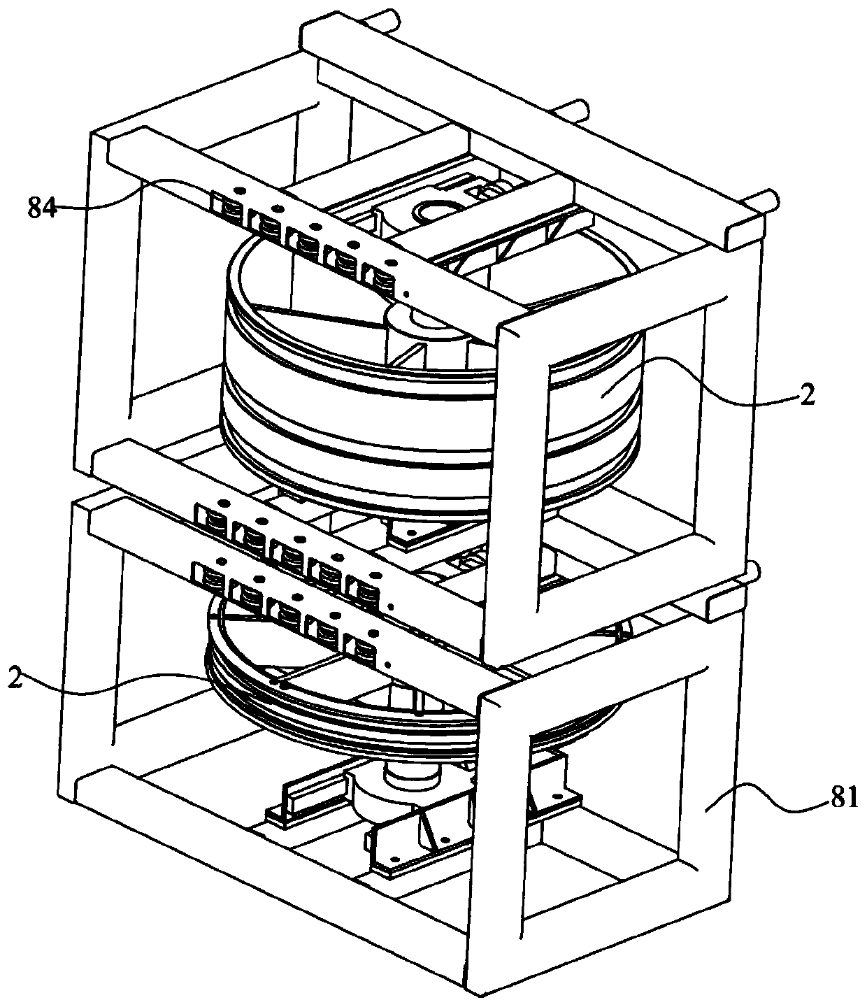
[0079] The feeding device 6 is used for loading the circuit board 13 to be electroplated.
[0080] The unloading device 7 is used for unloading the electroplated circuit board 13 .
[0081] An electroplating tank, located between the feeding device 6 and the unloading device 7, is used to form an electroplating layer on the circuit board 13 to be electroplated when the circuit board 13 to be electroplated passes through. as well as
[0082] The conveying structure of the circuit board 13 described in the first embodiment is used to drive the circuit board 13 to be electroplated from the feeding device 6 to the unloading device 7 through the electroplating tank.
[0083] In the above-mentioned electroplating equipment, the circuit board 13 is loaded on the conveying structure of the circuit board 13 through the action of the feeding device 6, and then the plating ...
PUM
Abstract
The invention provides a circuit board conveying structure. The circuit board conveying structure comprises a first transmission mechanism, a second transmission mechanism, at least one clamp, at least one material clamp and a driving mechanism, wherein the first transmission mechanism and the second transmission mechanism are arranged in parallel in the vertical direction; the at least one clampis arranged on the first transmission mechanism, is used for clamping the upper end of a circuit board and can be driven by the first transmission mechanism to move synchronously with the first transmission mechanism; the at least one material clamp is arranged on the second transmission mechanism and under the corresponding clamps, is used for clamping the lower end of the circuit board, and canbe driven by the second transmission mechanism to move synchronously with the second transmission mechanism, and the operating speed of the clamps are the same as that of the material clamps; and thedriving mechanism is connected with the first transmission mechanism and the second transmission mechanism and drives the first transmission mechanism and the second transmission mechanism to move synchronously. By means of the circuit board conveying structure, the lower end of the circuit board does not lag behind the upper end of the circuit board, and the board surface of the circuit board isprevented from being wrinkled in the conveying process.
Description
technical field [0001] The invention relates to the technical field of circuit board electroplating technology equipment, in particular to a circuit board conveying structure and electroplating equipment. Background technique [0002] The circuit board can be called a printed circuit board (PCB, Printed Circuit Board) or a printed circuit board (FPC, Flexible Printed Circuit board). The FPC circuit board is also called a flexible circuit board. The flexible circuit board is made of polyimide or polyester film A printed circuit board with high reliability and excellent flexibility made of base material. During the electroplating process, circuit boards often need to be electroplated with different thicknesses of electroplating solutions. Before electroplating, circuit boards of different thicknesses need to be clamped by clamps to maintain the verticality of the circuit boards in the electroplating bath, thereby ensuring the quality of electroplating. [0003] Chinese patent...
Claims
Application Information
Patent Timeline
Application Date:The date an application was filed.
Publication Date:The date a patent or application was officially published.
First Publication Date:The earliest publication date of a patent with the same application number.
Issue Date:Publication date of the patent grant document.
PCT Entry Date:The Entry date of PCT National Phase.
Estimated Expiry Date:The statutory expiry date of a patent right according to the Patent Law, and it is the longest term of protection that the patent right can achieve without the termination of the patent right due to other reasons(Term extension factor has been taken into account ).
Invalid Date:Actual expiry date is based on effective date or publication date of legal transaction data of invalid patent.

