A direct reduction process for producing sponge iron using converter gas

A converter gas and sponge iron technology, applied in furnaces, shaft furnaces, furnace types, etc., can solve the problems of long process route, low equipment investment, large equipment investment, etc., achieve low energy consumption and equipment investment, reduce dust content The effect of simple quantity and process flow

Active Publication Date: 2020-08-04
CHONGQING TECH & BUSINESS UNIV
View PDF6 Cites 0 Cited by
  • Summary
  • Abstract
  • Description
  • Claims
  • Application Information

AI Technical Summary

Problems solved by technology

[0005] The object of the present invention is to propose a direct reduction process for the production of sponge iron by utilizing converter gas, aiming at the problems of long process flow, large equipment investment and high energy consumption in the current production of sponge iron by converter gas. Solid carbon in consolidated carbonaceous pellets and CO in reducing gas obtained based on converter gas 2 、H 2 O generates C+CO in the gas-based direct reduction shaft furnace 2 =2CO and C+H 2 O=CO+H 2 The endothermic reaction improves the reduction performance of the reducing gas and at the same time makes the reducing gas temperature drop rapidly to the temperature range required for the gas-based direct reduction shaft furnace reduction, and the production of sponge iron is carried out. Ensure the pellet strength and metallurgical properties of cold-consolidated carbon-containing pellets to ensure the stable operation of the gas-based direct reduction shaft furnace, with simple process flow, low energy consumption and equipment investment

Method used


Image

  • A direct reduction process for producing sponge iron using converter gas

Examples


no. 1 example

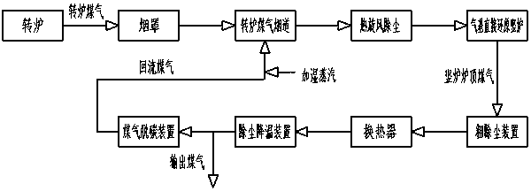
[0040] 1) The high-temperature converter gas discharged from the converter enters the converter gas flue through the fume hood, and mixes with the return gas after the shaft furnace top gas has been dedusted, cooled and decarburized, so that the temperature of the gas in the converter gas flue drops to 1050°C, from The 1050°C high-temperature gas coming out of the converter gas flue is dedusted by a hot cyclone and enters the gas-based direct reduction shaft furnace to reduce low-allocation carbon and cold-consolidate carbon-containing pellets to produce sponge iron and generate shaft furnace top gas.

[0041] 2) In the above step 1), the temperature of the high-temperature converter gas discharged from the converter is 1400°C.

[0042] 3) In the above step 1), after the top gas of the shaft furnace is dedusted and cooled by the coarse dedusting device, heat exchanger and dedusting and cooling device, part of it enters the gas decarbonization device to remove CO 2 Finally, it ...

no. 2 example

[0054] 1) The high-temperature converter gas discharged from the converter enters the converter gas flue through the fume hood, and mixes with the return gas after the shaft furnace top gas has been dedusted, cooled and decarburized, so that the temperature of the gas in the converter gas flue drops to 1075°C, from The high-temperature gas at 1075°C coming out of the converter gas flue is dedusted by a hot cyclone and enters the gas-based direct reduction shaft furnace to reduce low-allocation carbon and cold-consolidate carbon-containing pellets to produce sponge iron and generate shaft furnace top gas.

[0055] 2) In the above step 1), the temperature of the high-temperature converter gas discharged from the converter is 1550°C.

[0056] 3) In the above step 1), after the top gas of the shaft furnace is dedusted and cooled by the coarse dedusting device, heat exchanger and dedusting and cooling device, part of it enters the gas decarbonization device to remove CO 2 Finally, ...

no. 3 example

[0068] 1) The high-temperature converter gas discharged from the converter enters the converter gas flue through the fume hood, and mixes with the return gas after the shaft furnace top gas has been dedusted, cooled and decarburized, so that the temperature of the gas in the converter gas flue drops to 1100 ° C, from The 1100°C high-temperature gas coming out of the converter gas flue is dedusted by a hot cyclone and enters the gas-based direct reduction shaft furnace to reduce low-allocation carbon and cold-consolidate carbon-containing pellets to produce sponge iron and generate shaft furnace top gas.

[0069] 2) In the above step 1), the temperature of the high-temperature converter gas discharged from the converter is 1650°C.

[0070] 3) In the above step 1), after the top gas of the shaft furnace is dedusted and cooled by the coarse dedusting device, heat exchanger and dedusting and cooling device, part of it enters the gas decarbonization device to remove CO 2 Finally, i...


PUM

PropertyMeasurementUnit
particle sizeaaaaaaaaaa

Abstract

The invention discloses a direct reduction process for producing sponge iron by using converter gas. The direct reduction process is characterized in that high-temperature converter gas discharged from the converter enters a converter gas flue through a smoke hood, and is mixed with returned gas after dust removal, cooling and decarbonization of the furnace top gas of a vertical furnace, so that the temperature of the gas in the converter gas flue is reduced to 1050-1100 DEG C, the high-temperature coal gas at the temperature of 1050-1100 DEG C from the converter gas flue is subjected to hot cyclone dust removal and then enters a gas-base direct reduction vertical furnace to reduce a low-distribution carbon cold-bonded carbon-containing pellet to produce the sponge iron, and the top gas ofthe furnace top of the vertical furnace is generated. According to the direct reduction process, solid carbon in the cold-solidified carbon-containing pellet and CO2 in the reducing gas entering thevertical furnace are utilized, H2O is subjected to a heat absorption reaction to ensure the temperature and the reducing atmosphere of the reducing gas, and meanwhile, the pellet strength and the metallurgical performance of the cold-solidified carbon-containing pellet are ensured through low-carbon-distribution and proper pellet particle size, the process is simple, and the energy consumption islow.

Description

technical field [0001] This patent belongs to the technical field of direct reduction ironmaking, and is a direct reduction process aimed at producing sponge iron with converter gas. Background technique [0002] Converter gas is an important secondary energy source for iron and steel enterprises. The heat recovery of high-temperature converter gas at 1400 ° C to 1650 ° C in the converter gas flue and the high value-added utilization of converter gas are of great significance for reducing production costs in iron and steel plants. Key issues of concern to enterprises. [0003] At present, the recovery of high-temperature converter gas heat energy is mainly carried out in the form of vaporization cooling flue + waste heat boiler, and the heat energy of converter gas is recovered in the form of high-temperature steam. Not high, low added value. In addition, the utilization of converter gas is currently mainly used for steel rolling heating gas, and its utilization value is l...

Claims


Application Information

Patent Timeline
Patent Type & Authority Patents(China)
IPC IPC(8): C21B13/02
CPCY02P10/122
Inventor 陈凌
Owner CHONGQING TECH & BUSINESS UNIV
Why Eureka
Try Eureka