Measurement target for characterizing shock wave speed of medium Z opaque material and method

A technology of transparent materials and shock waves, applied in the direction of instruments, etc., can solve the problems of incompatibility of measurement and large uncertainty, and achieve the effect of relaxing the requirements of experimental conditions, eliminating differences, and ensuring consistency and reliability

Pending Publication Date: 2019-06-28
LASER FUSION RES CENT CHINA ACAD OF ENG PHYSICS
View PDF8 Cites 1 Cited by
  • Summary
  • Abstract
  • Description
  • Claims
  • Application Information

AI Technical Summary

Problems solved by technology

[0005] Aiming at the deficiencies of the existing technology, a measurement target and method for characterization of the shock wave velocity in opaque materials are proposed to solve the problems of large uncertainty and incompatibility with formal experimental measurements in the current characterization of shock wave velocity stability.

Method used


Image

  • Measurement target for characterizing shock wave speed of medium Z opaque material and method
  • Measurement target for characterizing shock wave speed of medium Z opaque material and method
  • Measurement target for characterizing shock wave speed of medium Z opaque material and method

Examples


Embodiment 1

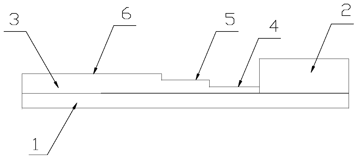
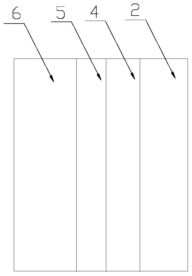
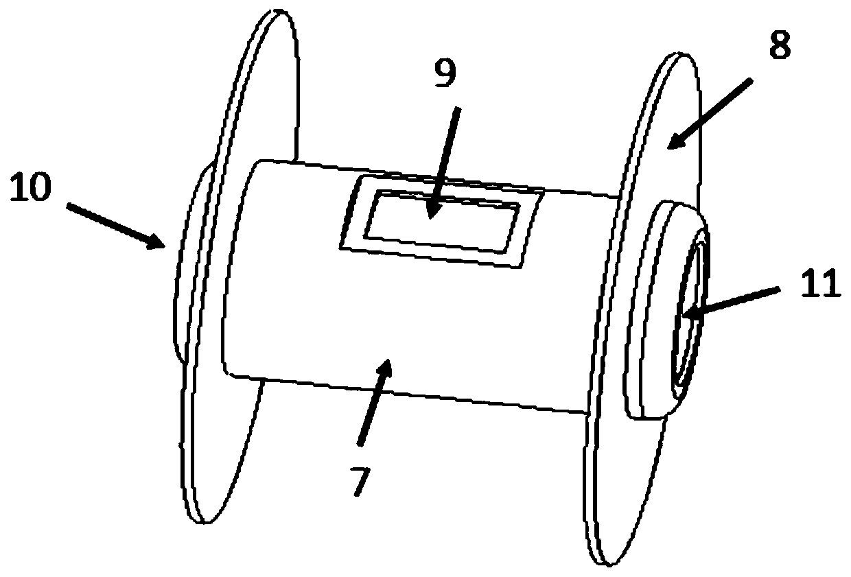
[0037] Such as Figure 1 to Figure 4 As shown, a measurement target for the shock wave velocity in an opaque material in middle Z is located at the diagnostic hole 9 of the driving black cavity 7. Specifically, the driving black cavity 7 is made of Au and has a straight cylindrical structure with upper and lower openings. The upper and lower openings are respectively used as laser injection port I10 and laser injection port II11, through which laser light enters the driving black cavity 7 to generate a uniform high-temperature X-ray radiation field. A disk-shaped shielding sheet 8 is arranged on the periphery of the driving black cavity 7 and at a distance of 100 μm from its upper and lower openings to block stray light. The shielding sheet 8 is made of Cu, and the surface of the shielding sheet 8 is coated with CH layer. The diagnosis hole 9 is located on the side wall of the driving black cavity 7 , and the measurement target 12 is placed on the diagnosis hole 9 . Meanwhile...

Embodiment 2

[0048] The same part of this embodiment and Embodiment 1 will not be described again, the difference is:

[0049] The length of the driving black cavity 7 is 2400 μm, the inner diameter is 1200 μm, the thickness of the cavity wall is 35 μm, and the diameters of laser injection port I10 and laser injection port II11 are 850 μm. The length of the diagnostic hole 9 a 0 =700μm, its width b 0 =400μm, then a 1 =b 1 = 900 μm, the minimum flat area width d of the default shock wave of the random reflector velocity interferometer is 100-120 μm, then 100 μm≤b 3 ≤120μm, 100μm≤b 4 ≤120μm, the target tolerance Δd is ±50μm, then 250μm≤b 2 ≤320μm, 340μm≤b 5 ≤450μm, the side sparse wave propagating to the center of the measurement target along the horizontal direction will cause the shock wave intensity to decrease, and at the same time produce the bending of the shock wave front. Therefore, compared with the first sample layer 4 and the second sample layer 5, the third The width of sa...

Embodiment 3

[0054] The same part of this embodiment and embodiment two will not be repeated, the difference is:

[0055] The incident laser wavelength is 0.351μm, the total input energy is 800J, and the power density is 5×10 13 W / cm 2 , the radiation temperature for driving the black cavity 7 is about 120eV, the sample layer 3 is an Al sample layer, and the tracer layer 2 is a CH tracer layer.

[0056] Figure 6 It is given that the velocity change from 20km / s to 25km / s in the Al sample layer in this embodiment is obtained by fluid dynamics simulation, the horizontal axis represents time, and the vertical axis represents velocity. Wherein, the solid triangle represents the velocity history of the shock wave in the CH tracer layer; the hollow triangle represents the velocity history of the shock wave measured by the present invention in the Al sample layer; the hollow circle represents the shock wave velocity history in the Al sample layer obtained by simulation calculation; Squares rep...


PUM


Abstract

The invention relates to a measurement target for characterizing shock wave speed of a medium Z opaque material and a method, and belongs to the technical field of high-pressure characteristics of thematerial. The measurement target is located at a diagnostic hole of a drive black cavity and comprises an ablation layer, a tracer layer and a sample layer, wherein the ablation layer is arranged toface the diagnostic hole; the tracer layer is made of a transparent material; the sample layer is a medium Z opaque material sample layer, is of a stepped structure and comprises a first sample layer,a second sample layer and a third sample layer which are arranged side by side in sequence, and the thicknesses of the first sample layer, the second sample layer and the third sample layer are increased in sequence. Compared with a traditional wedge-shaped sample, planar sample design is adopted, machining is easy, the machining precision is high, higher-precision measurement can be realized, the requirement for experimental conditions can be broadened to the greatest extent, an experimental result derives from the same driving source, possible difference of the experimental conditions between different times is eliminated, consistency and reliability of data are guaranteed, and meanwhile, experimental resources are saved.

Description

technical field [0001] The invention belongs to the technical field of high-voltage characteristics of materials, and in particular relates to a measurement target and method for characterizing shock wave velocity in medium-Z opaque materials. Background technique [0002] Under laboratory conditions, high-power lasers are widely used in experimental research on high-voltage characteristics of materials. The laser ablates the sample and generates a high-speed shock wave in the sample, which compresses the sample to a high pressure state. Compared with traditional loading methods, such as gas cannon, laser can realize the loading of samples in a higher pressure range. [0003] In the experiment, the compression state of the sample was quantitatively diagnosed by measuring the shock wave velocity and other physical quantities, combined with the impedance matching method. Considering that the range of pressure generated in the sample can be directly related to the velocity of...

Claims


Application Information

Patent Timeline
Patent Type & Authority Applications(China)
IPC IPC(8): G01J11/00
Inventor 张琛段晓溪章欢刘浩杨为明叶青孙亮王哲斌理玉龙刘祥明关赞洋杨冬丁永坤
Owner LASER FUSION RES CENT CHINA ACAD OF ENG PHYSICS
Why Eureka
Try Eureka